Objective optical system

Active Publication Date: 2010-05-20
EVIDENT CORP
View PDF4 Cites 117 Cited by
  • Summary
  • Abstract
  • Description
  • Claims
  • Application Information

AI Technical Summary

Benefits of technology

[0011]The present invention has been made in view of the above-described circumstances, and an object thereof is to provide an objective optical system that enables observation of living tissue, such as cells and muscles, and vario

Problems solved by technology

However, because such a wide incision of the living body is highly invasive, long-term observation is impossible.
However, this is still highly invasive when a deep part of a relatively small organ, such as the brain, of a mouse is to be observed, and, considering the damage to the living body, there is an inconvenience in that observation under normal conditions is difficult.
Furthermore, this optical system has problems not only in that it has a small numerical aperture for observation using multiphoton excitation, decreasing the resolution, but also in that it has a

Method used


Image

  • Objective optical system
  • Objective optical system
  • Objective optical system

Examples


first embodiment

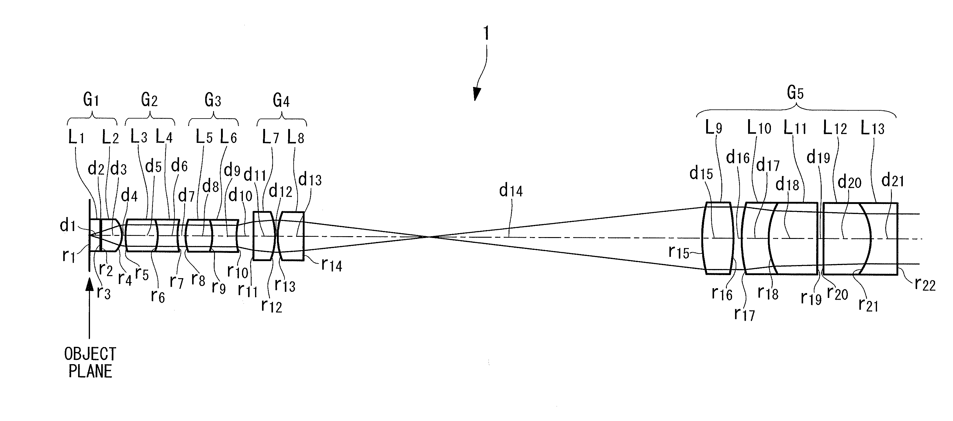
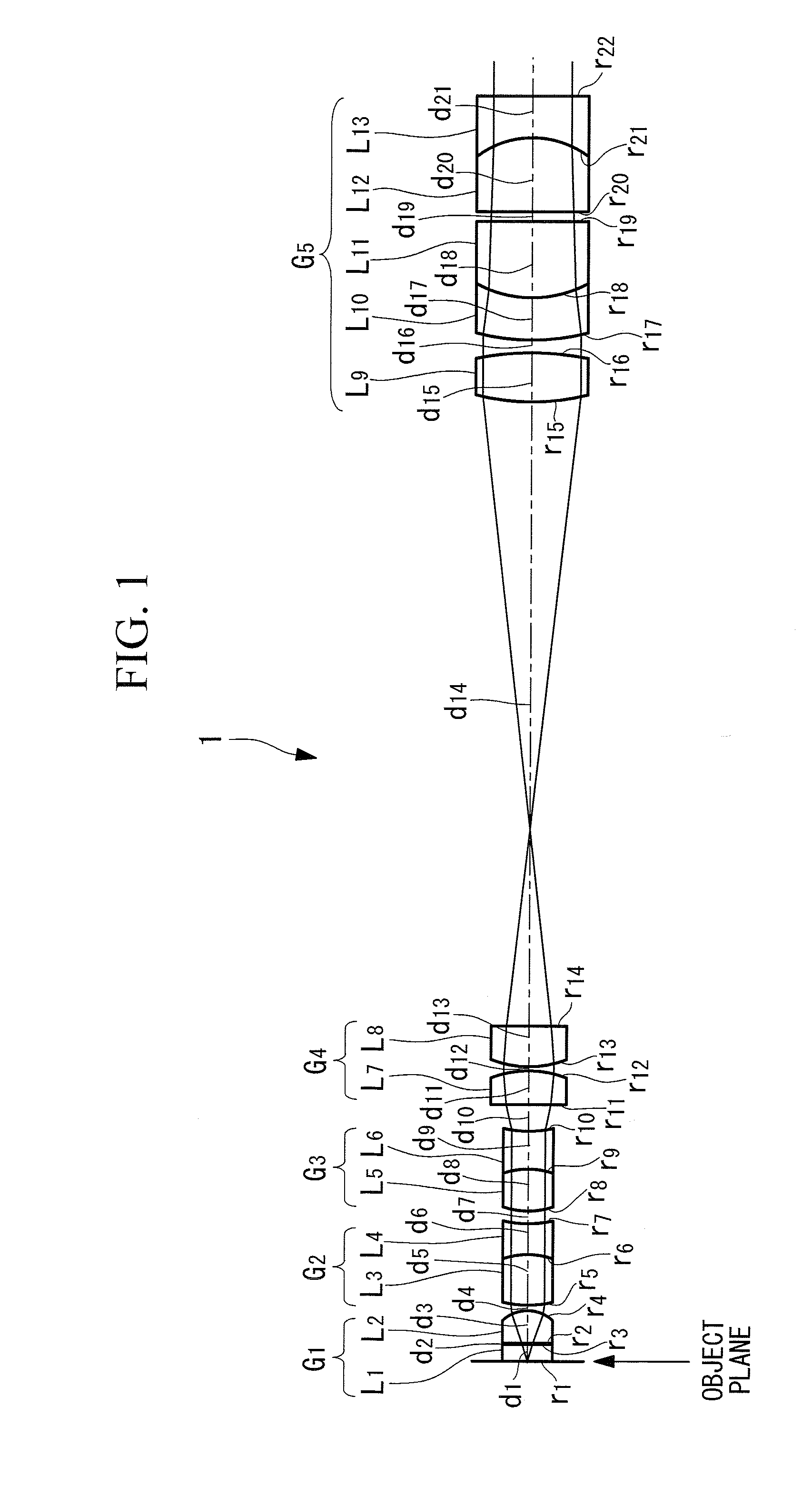
[0094]FIG. 1 shows the lens configuration according to a first embodiment of the present invention, and the first embodiment will be described below.

[0095]An immersion small-diameter objective optical system 1 according to this embodiment, designed to focus at infinity and having an intermediate image plane, includes a first group G1 having positive refractive power, including a lens disposed on the extreme object side, whose object-side lens surface is substantially flat, and a plano-convex lens with the convex surface facing towards the image plane side; a second group G2 having positive refractive power, whose extreme-object-side lens surface is a convex surface facing towards the object side; a third group G3 having negative refractive power, whose lens surface on the extreme image plane side is a concave surface facing towards the image plane side; a fourth group G4 having positive refractive power, whose lens surface, on the image plane side, of the lens disposed on the extrem...

second embodiment

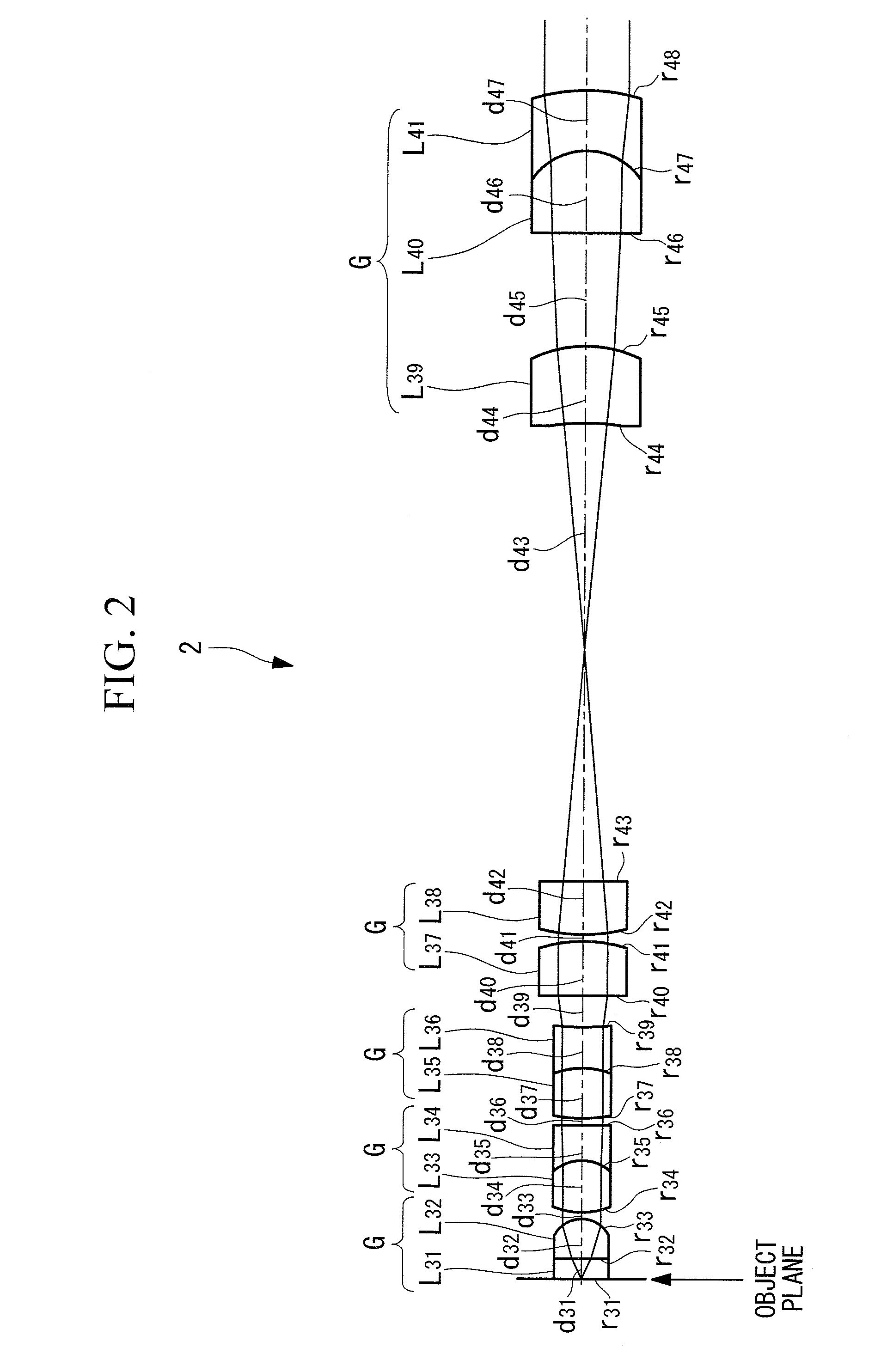
[0109]FIG. 2 shows the lens configuration according to a second embodiment of the present invention, and the second embodiment will be described below.

[0110]The structures that are common to those of the first embodiment will be denoted by the same reference numerals.

[0111]An objective optical system 2 according to this embodiment, designed to focus at infinity and having an intermediate image plane, includes a first group G1 having positive refractive power, including a lens disposed on the extreme object side, whose object-side lens surface is substantially flat, and a piano-convex lens with the convex surface facing towards the image plane side; a second group G2 having positive refractive power, whose extreme-object-side lens surface is a convex surface facing towards the object side; a third group G3 having negative refractive power, whose lens surface on the extreme image plane side is a concave surface facing towards the image plane side; a fourth group G4 having positive ref...

third embodiment

[0125]An objective optical system 3 according to a third embodiment of the present invention will be described with reference to the drawings.

[0126]The objective optical system 3 according to this embodiment is an immersion objective optical system designed to focus at infinity and having an intermediate image plane, as shown in FIGS. 6 and 7.

[0127]This objective optical system 3 includes a first lens group (first group) G1 having positive refractive power, including a lens disposed on the extreme object side, whose object-side lens surface is substantially flat, and a convex lens with the convex surface facing towards the image side; a second lens group (second group) G2 having positive refractive power, whose extreme-object-side lens surface is a convex surface facing towards the object side; a third lens group (third group) G3 having negative refractive power, whose extreme-image-side lens surface is a concave surface facing towards the image side; a fourth lens group (fourth gro...


PUM


Abstract

An objective optical system includes a first group having positive refractive power and a piano-convex lens with the convex surface facing the image side; a second group having positive refractive power and a lens whose extreme-object-side lens surface is a convex surface facing the object side; a third group having negative refractive power and a lens whose extreme-image-side lens surface is a concave surface facing the image side; a fourth group having positive refractive power and a lens disposed on the extreme object side, whose image-side lens surface is a convex surface facing the image side and a lens disposed on the extreme image side, whose object-side lens surface is a convex surface facing the object side; and a fifth group having positive refractive power and a combined lens formed by joining a convex lens and a concave lens, the joined surface having negative refractive power.

Description

CROSS REFERENCE TO RELATED APPLICATIONS[0001]This application claims benefit of Japanese Applications No. 2008-295713 filed in Japan on Nov. 19, 2008 and No. 2009-221390 filed in Japan on Sep. 25, 2009, the contents of each of which are hereby incorporated by their reference.BACKGROUND OF THE INVENTION[0002]1. Field of the Invention[0003]The present invention relates to an objective optical system.[0004]2. Description of Related Art[0005]Conventionally, microscopic observation using an objective optical system is widely used. For example, in order to observe the behavior or the like of biological molecules in cells and tissue of cultured organisms using images, a method in which specific molecules, tissue, cells, or the like tagged with a colorant or fluorescent marker are observed with a fluorescence microscope, a confocal laser scanning microscope, or the like is known. In recent years, because the behavior of molecules of living mammal organisms, such as mice, is sometimes differ...

Claims


Application Information

Patent Timeline
IPC IPC(8): G02B21/02
CPCA61B1/002A61B2503/40G02B21/02A61B1/313
Inventor FUJIWARA, MASATO
Owner EVIDENT CORP
Why Eureka
Try Eureka