
Microphere-containing insulation

a technology of micropheres and insulation layers, applied in mechanical equipment, chemistry equipment and processes, transportation and packaging, etc., can solve the problems of reduced oil flow, increased heat loss from the oil present in the pipe, and unfilled polymer layers that typically exhibit higher volume shrinkage, so as to achieve less volume shrinkage and/or thermal expansion coefficient mismatch, and high volumetric heat capacity. , the effect of less volume shrinkag

Inactive Publication Date: 2010-05-27
3M INNOVATIVE PROPERTIES CO
View PDF36 Cites 20 Cited by
  • Summary
  • Abstract
  • Description
  • Claims
  • Application Information

AI Technical Summary

Benefits of technology

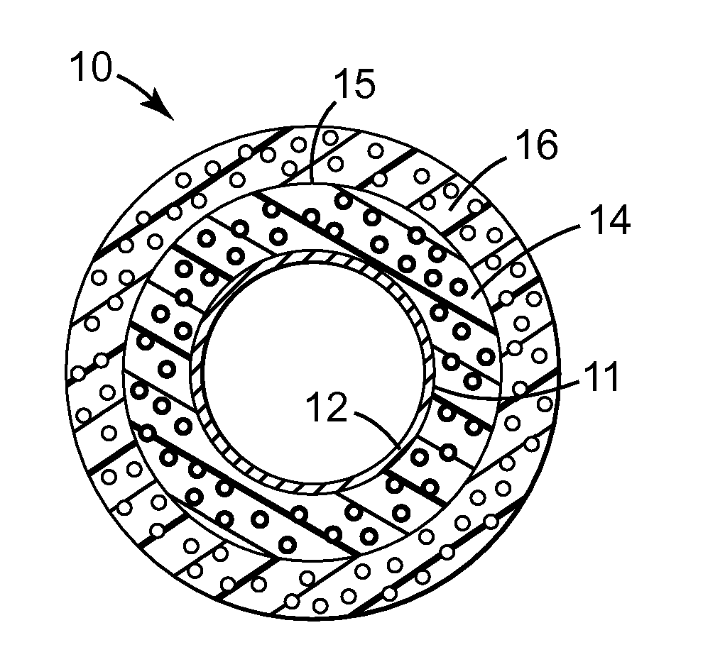
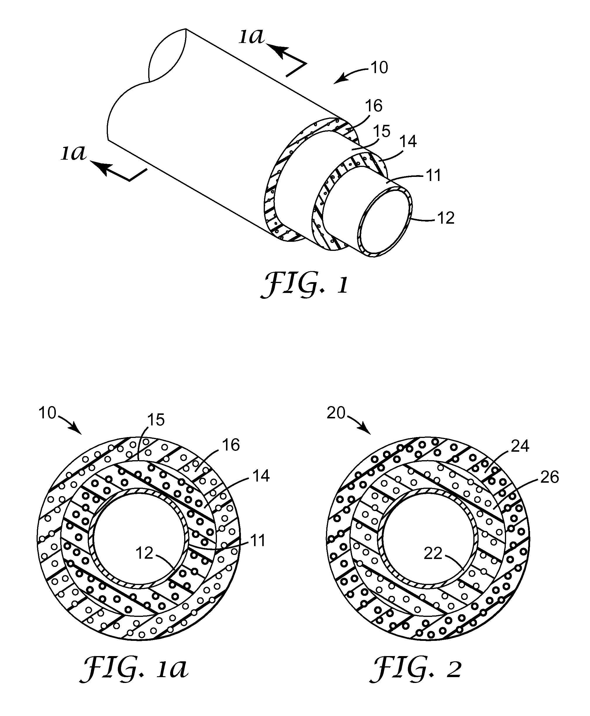
The present invention provides an insulated article with two layers of insulation, each with its own thermal conductivity and volumetric heat capacity. The first layer is made of a polymeric material and hollow ceramic microspheres, while the second layer is made of a different polymeric material and hollow ceramic microspheres. The first and second layers can be made from the same or different thermoplastics or thermosets. The invention also provides a method for making the insulated article by generating requirements data for the insulation layers and formulating compositions based on the requirements data. The invention can improve the thermal insulation of the article and provide better protection against heat transfer.

Problems solved by technology

In these pipelines or flowlines, the temperature of the surrounding water can be less than 10° C., which can lead to extensive heat loss from the oil present in the pipe.
Such heat loss can result in a reduction of the flow of oil due to an increase in viscosity of the oil and / or precipitation of paraffins and / or asphaltenes present in the oil.
However, unfilled polymer layers typically exhibit higher volume shrinkage and / or have higher coefficients of thermal expansion than typical syntactic foams, which could cause stresses within or between the insulation layers.
One solution to the problem of shrinkage in an unfilled polypropylene insulation layer is to add solid glass beads to the polypropylene; however, this composition tends to have excessive thermal conductivity.

Method used


Image

  • Microphere-containing insulation
  • Microphere-containing insulation

Examples


example

Thermal Requirements for a First Insulation Region

[0051]A composition having a volumetric heat capacity and thermal conductivity that approach or generally match that of unfilled polypropylene was desired.

[0052]A Fox50 Heat Flow Meter (obtained from LaserComp, Saugus, Mass.) was used to measure the thermal conductivity of a 12.7 mm thick sheet of unfilled polypropylene having a density of 0.923 g / cm3 (obtained from W. W. Grainger, Inc., Houston, Tex.) at a mean temperature of 37.5° C. (hot side temperature of 50° C., cold side temperature of 25° C.). The instrument was operated using polymethyl methacrylate calibration (available from Lucite International, Memphis, Tenn., under the trade designation “PERSPEX”) in accordance with the ASTM standard C518-98 “Standard Test Method for Steady-State Thermal Transmission Properties by Means of the Heat Flow Meter Apparatus,” which is incorporated herein by reference. The thermal conductivity was 0.238 W / mK on the upper plate and 0.225 W / mK ...


PUM

PropertyMeasurementUnit
densityaaaaaaaaaa
densityaaaaaaaaaa
depthaaaaaaaaaa

Abstract

An insulated article having a first insulation region comprising a first polymeric material and first hollow ceramic microspheres and a second insulation region comprising a second polymeric material and second hollow ceramic microspheres. The first insulation region has a thermal conductivity that is no greater than the thermal conductivity of the first polymeric material and a volumetric heat capacity in a range of 60% to 90% of the volumetric heat capacity of the first polymeric material. The second insulation region has a thermal conductivity that is no greater than 90% of the thermal conductivity of the second polymeric material and a volumetric heat capacity that is less than 60% of the volumetric heat capacity of the second polymeric material. A method for making a composition for insulating an article is also described.

Description

BACKGROUND[0001]Syntactic foams containing hollow ceramic microspheres are used for insulation in a variety of applications due in part to their low thermal conductivities. For example, syntactic foams are used in wet insulation applications (i.e., insulation that is exposed to sea water) for off-shore oil pipelines or flowlines. In these pipelines or flowlines, the temperature of the surrounding water can be less than 10° C., which can lead to extensive heat loss from the oil present in the pipe. Such heat loss can result in a reduction of the flow of oil due to an increase in viscosity of the oil and / or precipitation of paraffins and / or asphaltenes present in the oil. Some wet insulation systems combine unfilled polymer layers with syntactic foam layers in order to maintain the temperature of the oil in the pipelines or flowlines as close to the production temperature as possible. However, unfilled polymer layers typically exhibit higher volume shrinkage and / or have higher coeffic...

Claims


Application Information

Patent Timeline
Patent Type & Authority Applications(United States)
IPC IPC(8): F16L9/14B32B5/02B32B1/08C09K5/00
CPCC04B26/04C04B26/10C04B2111/00612F16L59/021C04B14/24C04B14/301Y10T428/249974Y10T428/249961
Inventor D'SOUZA, ANDREW S.HUNTER, ROBERT W.URQUIOLA, MARIA B.
Owner 3M INNOVATIVE PROPERTIES CO
Learn More