Heating and sterilizing apparatus and method of using same

a technology of sterilizing apparatus and heat exchanger, which is applied in the direction of lighting and heating apparatus, cleaning using liquids, weed killers, etc., can solve the problems of slow natural convection, non-uniformity and distortion, and achieve the effect of minimizing gas flow, maximizing heat transfer to the gas, and minimizing deformation of the coil

a technology of sterilizing apparatus and heat exchanger, which is applied in the direction of lighting and heating apparatus, cleaning using liquids, weed killers, etc., can solve the problems of slow natural convection, non-uniformity and distortion, and achieve the effect of minimizing gas flow, maximizing heat transfer to the gas, and minimizing deformation of the coil

US20100129157A1Active Publication Date: 2010-05-27MHI HEALTH DEVICES

Image

  • Heating and sterilizing apparatus and method of using same
  • Heating and sterilizing apparatus and method of using same
  • Heating and sterilizing apparatus and method of using same

Examples


experiment 1

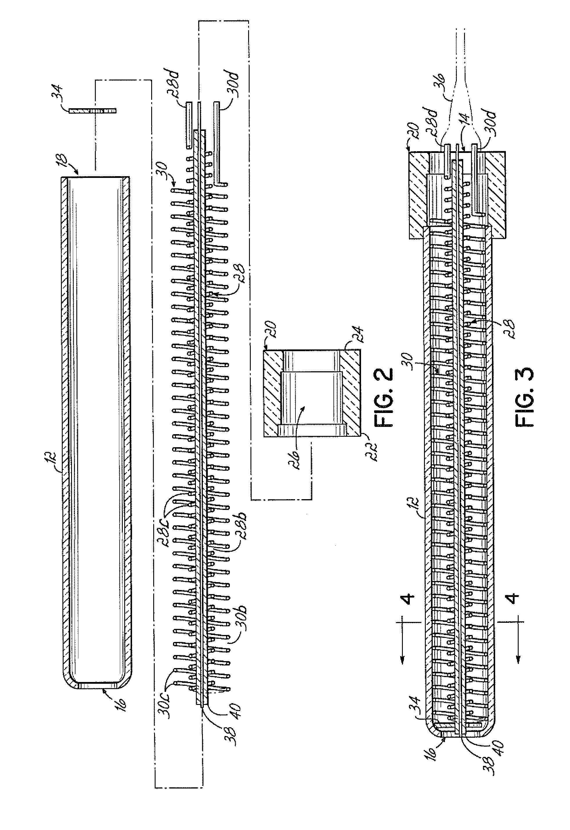
[0065]The outer coil 30 provides rifling of the gas that increases heat transfer from the coil to the gas. A helical coil wire 30a of 240 mm long and 13.2 mm mean diameter, working out for 8.2 Ohms (18SWG A1 commercial wire) was used for testing. The coil was inserted in an open-ended ceramic tube 12. The exit end of the coil was brought back to the inlet side through a ceramic insulating tube. The coil was operated at 110V, at a power rating of 1.47 kW. The airflow was maintained at 5 SCFM at 0.4 Kgs / cm2 working pressure. The exit temperature of the air stabilized at 560° C.

experiment 2

[0066]The inner coil 28 overcomes the conda surface effect, and provides for annular area heating of the gas, which provides for the highest heat transfer to the gas. The exit end of the coil 28 was wound on its return on the ceramic insulating tubular housing 12. The resulting coil resistance was 10.8 Ohms. The coil 28 was operated with the same airflow, air pressure and operating voltage of 110V as in Experiment 1. The coil now operated at 1.1 kW, and the exit temperature stabilized at 806° C.

experiment 3

[0067]The inner coil 28 was wound in the opposite direction of the outer coil 30 to provide opposite rifling to the gas with respect to the outer coil. This causes a turbulence effect on the airflow, which increases heat transfer to the gas. All other parameters were the same as Experiment 2. The exit temperature stabilized at 845° C. Therefore, the opposite winding configuration gave a nearly 50° C. higher temperature. Table 1 below gives further experimental details and exit temperatures.


PUM


Abstract

An apparatus (200, 300, 400) for generating superheated steam capable of reducing or eliminating microorganisms associated with an item (230) includes a gas heater (10) for heating a gas, a steam generator coupled to the gas heater (10) and having a reservoir (216, 304) for supplying water, wherein the heater (10) heats the gas such that when water is combined therewith, a mixture of superheated steam and gas capable of reducing or eliminating microorganisms is discharged from the apparatus (200, 300, 400). The generation of the steam-gas mixture may be done at one atmosphere of pressure and the mixing may be done prior to expelling the fluid from the apparatus (200, 300, 400). The apparatus (400) may be configured as a hand-held device, A method of treating an item (230) for microorganisms includes generating a superheated steam at approximately one atmosphere of pressure, directing a flow of the steam onto the item (230), and reducing or eliminating microorganisms using the steam.

Description

CROSS-REFERENCE TO RELATED APPLICATIONS[0001]This is a continuation-in-part application of U.S. patent application Ser. No. 11 / 682,107 filed on Mar. 5, 2007, which claimed the benefit of U.S. Provisional Patent Application Ser. No. 60 / 832,608 filed on Jul. 24, 2006; which is a continuation-in-part application of U.S. patent application Ser. No. 10 / 703,497 filed on Nov. 10, 2003, which claimed the benefit of U.S. Provisional Patent Application Ser. No. 60 / 438,321 filed on Jan. 7, 2003, each of which is hereby incorporated by reference herein in its entirety. This application also claims the benefit of U.S. Provisional Application Ser. No. 60 / 858,944 filed on Nov. 15, 2006; U.S. Provisional Application Ser. No. 60 / 901,007 filed on Feb. 9, 2007; U.S. Provisional Application Ser. No. 60 / 907,944 filed on Apr. 24, 2007; U.S. Provisional Application Ser. No. 60 / 924,958 filed on Jun. 4, 2007; U.S. Provisional Application Ser. No. 60 / 929,637 filed on Jul. 6, 2007; U.S. Provisional Applicatio...

Claims


Application Information

Patent Timeline
27 May 2010
Publication
US20100129157A1
IPC
A61L2/07; A61L2/20; B09C1/02
CPC
A01M17/002; A01M21/04; A61L2/07; A61L2202/15; A61L2202/16; A61L2202/17; F24H3/002; B08B2230/01
Inventors
REDDY, GANTA S.; VISSA, RAMGOPAL