Solar cell, concentrating solar power generation module, concentrating solar power generation unit, method of manufacturing solar cell, and solar cell manufacturing apparatus

a technology of solar cells and manufacturing methods, applied in semiconductor devices, layered products, chemical instruments and processes, etc., can solve the problems of reducing the electric power (output) generated by the solar cell element , unable to make efficient use of sunlight, and actual amount of light incident on the solar cell, etc., to achieve stable manufacturing process, high heat resistance, and easy and reliable manufacturing

Inactive Publication Date: 2010-06-03
SHARP KK
View PDF19 Cites 24 Cited by
  • Summary
  • Abstract
  • Description
  • Claims
  • Application Information

AI Technical Summary

Benefits of technology

[0101]In the solar cell of the present invention, because a covering portion that covers a solar cell element placed on a receiver substrate is configured from a sealing frame that surrounds the periphery of the solar cell element, a light-transmitting covering plate that is bonded to the sealing frame and that covers the solar cell element, and a resin sealing portion that is formed in a sealing region defined by the sealing frame and the light-transmitting covering plate, the solar cells can be manufactured readily and reliably with a stable manufacturing process, and the effects of obtaining high heat resistance and high moisture resistance and improving mass productivity and reliability can be achieved. In addition, it is possible to achieve the significant effects of providing a concentrating solar cell, in which sunlight having a high energy density is directed by a concentrating lens, at a lower cost.
[0102]According to the method of manufacturing a solar cell of the present invention, a covering portion forming step of forming a covering portion that covers a solar cell element placed on a receiver substrate involves a sealing frame forming step of forming a sealing frame that surrounds the periphery of the solar cell element, a covering plate bonding step of bonding a light-transmitting covering plate covering the solar cell element to the sealing frame, and a resin sealing step of filling a sealing region with sealing resin to form a resin sealing portion. Accordingly, the covering portion that protects the solar cell element can be formed readily and reliably with good productivity, and the effects of a high yield and high productivity can be achieved.
[0103]According to the solar cell manufacturing apparatus of the present invention, a solar cell manufacturing apparatus that fills a sealing region defined by a sealing frame surrounding the periphery of a solar cell element placed on a receiver substrate and a light-transmitting covering plate bonded to the sealing frame with sealing resin so as to form a resin sealing portion is configured from a substrate juxtaposition jig in which a plurality of receiver substrates are juxtaposed with an opening of the sealing frame being positioned in an upper portion of the sealing frame and a resin injector that fills the sealing region with sealing resin through the opening. Accordingly, the resin sealing portion can be formed readily and rapidly with good productivity, and the effect of manufacturing a solar cell with good productivity can be achieved.
[0104]Alternatively, according to the solar cell of the present invention, a solar cell element is placed on a receiver substrate including a base, an intermediate insulating layer laminated on the base and a connection pattern layer laminated on the intermediate insulating layer, and an external connecting terminal of the solar cell element is drawn from the connection pattern layer. Accordingly, the base can be utilized effectively as a heat dissipating means by insulating the solar cell element from the base, so the effects of high insulation capabilities, heat dissipation properties, high reliability and high power-generation efficiency can be achieved with a simple structure.
[0105]In other words, the solar cell according to the present invention has high insulation capabilities and heat dissipation properties with a simple structure, so a significant effect is obtained by applying it as a solar cell in which a concentrating solar cell element, to which concentrated sunlight is directed, is placed.
[0106]Furthermore, according to the concentrating solar power generation unit of the present invention, a receiver substrate on which a solar cell element is placed is fixed to a solar cell mounting plate, and a radiator is disposed on the back face side of the receiver substrate that is opposite to the surface side on which the solar cell element is placed so as to correspond to the solar cell element. Accordingly, the heat generated by the sunlight concentrated and directed to the solar cell element can be dissipated through the receiver substrate and the radiator, so the effect of heat dissipation properties, good productivity and high power-generation efficiency with a simple heat dissipation structure can be obtained.

Problems solved by technology

However, if the position of the solar cell element remains fixed, most sunlight enters obliquely, failing to make efficient use of the sunlight.
In reality, however, alignment errors between the concentrating lens 142 and the solar cell element 111, positional offset caused by the difference in temperature properties between the members that constitute the concentrating solar power generation module 140m, and the like occur, so the apparatus has a problem in that the actual amount of light incident on the solar cell element 111 decreases, reducing the electric power (output) generated by the solar cell element 111.
There is also another problem in that when a region other than the solar cell element 111 is irradiated with deviated sunlight Ls (sunlight Lss), the thermal energy of the deviated sunlight Lss heats the members of the irradiated portion (for example, insulating film, wiring, etc.) to a high temperature, causing burnout (breakage) in some cases.

Method used


Image

  • Solar cell, concentrating solar power generation module, concentrating solar power generation unit, method of manufacturing solar cell, and solar cell manufacturing apparatus
  • Solar cell, concentrating solar power generation module, concentrating solar power generation unit, method of manufacturing solar cell, and solar cell manufacturing apparatus
  • Solar cell, concentrating solar power generation module, concentrating solar power generation unit, method of manufacturing solar cell, and solar cell manufacturing apparatus

Examples


embodiment 1

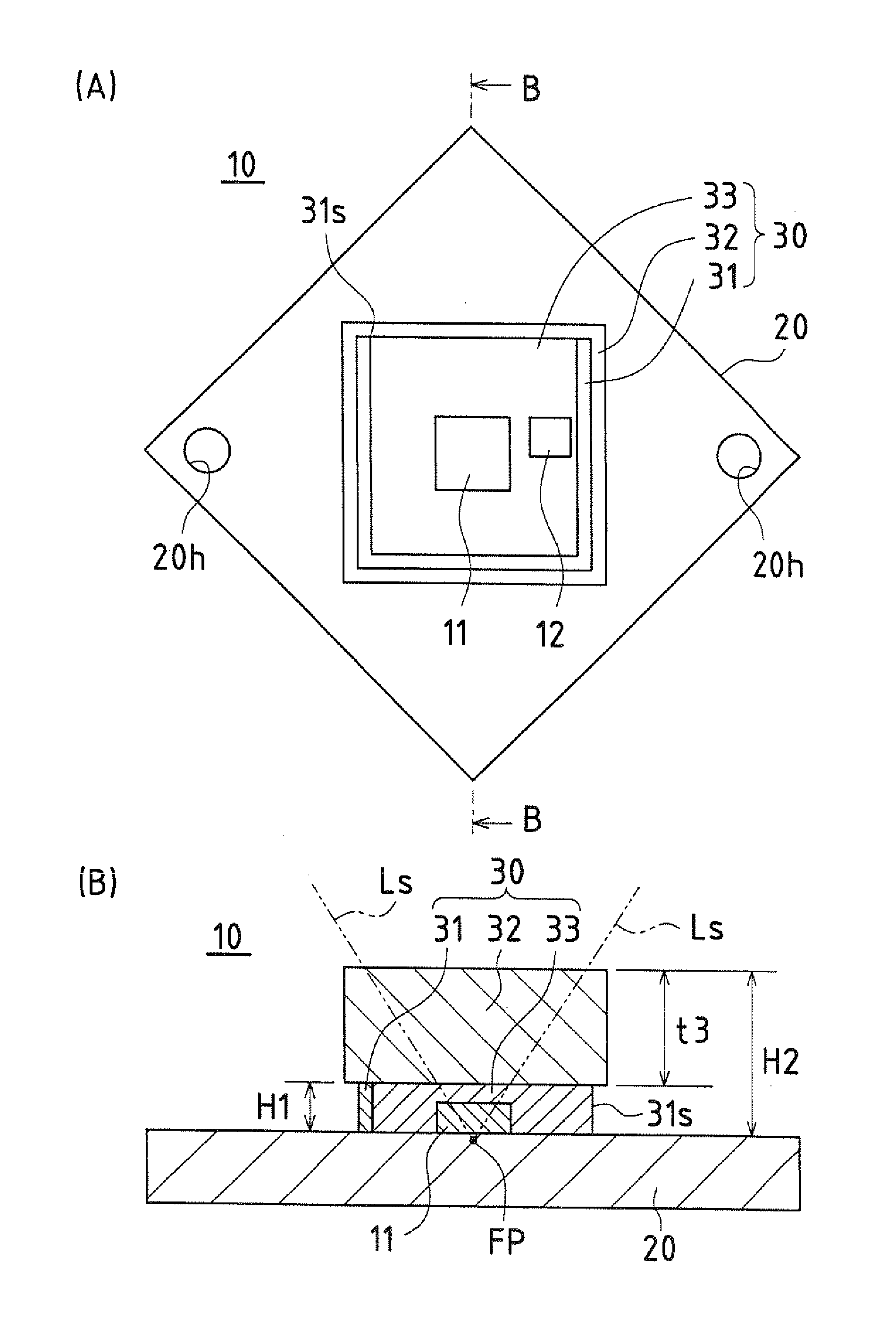
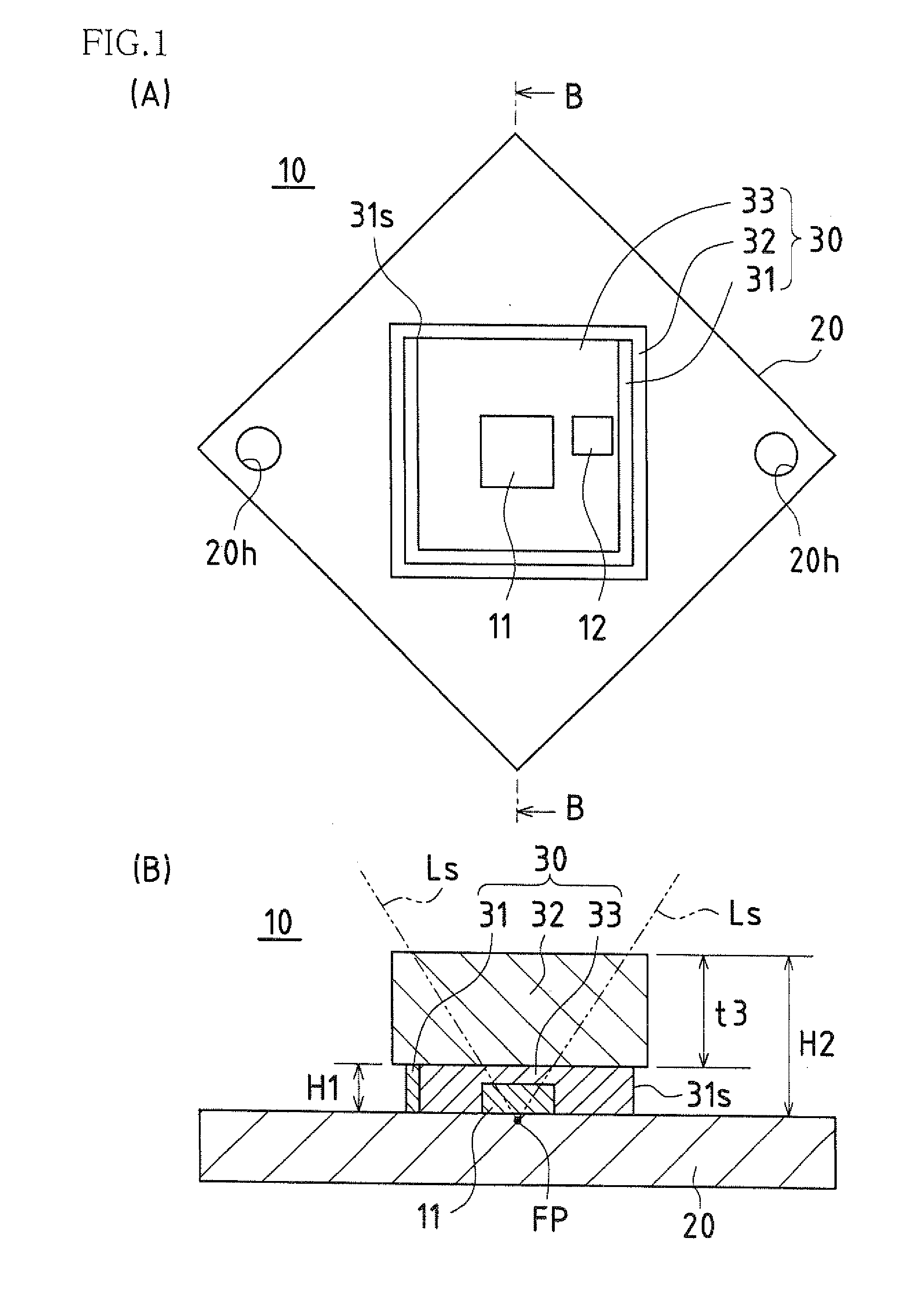
[0206]FIG. 1 is an explanatory diagram illustrating an overall configuration of a solar cell according to Embodiment 1 of the present invention, with FIG. 1(A) being a plan view of the solar cell in which a solar cell element is placed on a receiver substrate, and FIG. 1(B) being a cross-sectional view of the cross section taken along the line B-B of FIG. 1(A).

[0207]A solar cell 10 according to Embodiment 1 includes a concentrating solar cell element 11 that generates power by converting directed sunlight Ls concentrated by a concentrating lens (not shown) into electricity, and a receiver substrate 20 on which the solar cell element 11 is placed. The solar cell element 11 is disposed on a center portion of the receiver substrate 20 in consideration of the uniform dissipation of heat.

[0208]A bypass diode 12 is connected to the solar cell element 11 in parallel. The bypass diode 12 secures a current path in the case where the solar cell element 11 acts as a resistor when sunlight Ls i...

embodiment 2

[0229]A method of manufacturing the solar cell according to Embodiment 1 of the present invention will be described as Embodiment 2 (a solar cell manufacturing method) of the present invention with reference to FIGS. 2 to 12.

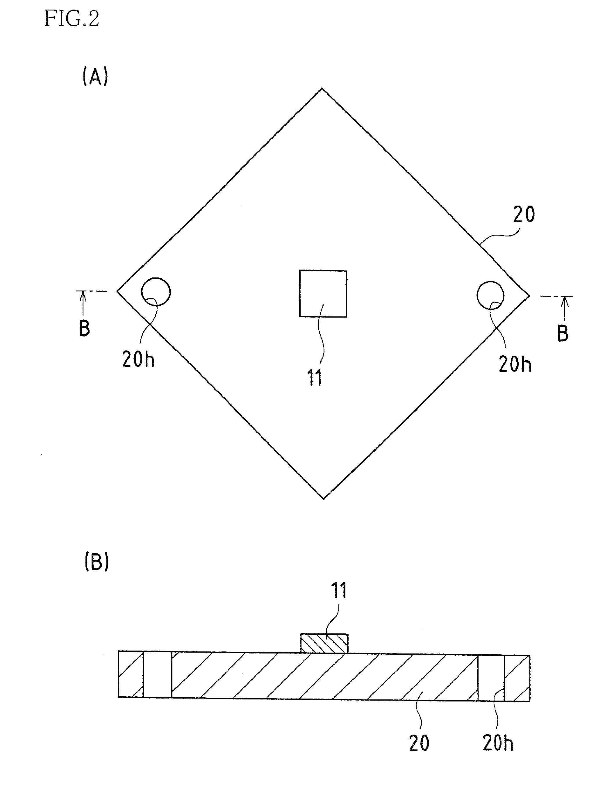
[0230]FIG. 2 is a process explanatory diagram illustrating a process of the method of manufacturing a solar cell according to Embodiment 2 of the present invention. FIG. 2(A) is a plan view showing a solar cell element placed on a receiver substrate, and FIG. 2(B) is a cross-sectional view showing the cross section taken along the line B-B of FIG. 2(A).

[0231]A solar cell element 11 is attached to a center portion (connection pattern layer) of a receiver substrate 20 by soldering. So as to simplify the drawings, a bypass diode 12 is not shown, but the bypass diode 12 is also attached to the receiver substrate 20 by soldering, as in the case of the solar cell element 11. As in Embodiment 1, the surface electrode of the solar cell element 11, the connection pattern...

embodiment 3

[0290]A solar cell according to Embodiment 3 of the present invention will be described with reference to FIGS. 13(A) to 14.

[0291]FIGS. 13(A) and 13(B) are explanatory diagrams illustrating a solar cell according to Embodiment 3 of the present invention. FIG. 13(A) is a plan view and FIG. 13(B) is a cross-sectional view showing a state of the cross section taken along the line B-B of FIG. 13(A). FIG. 14 is an enlarged plan view showing a state of the surface electrode of the solar cell element shown in FIGS. 13(A) and 13(B).

[0292]A solar cell 10A of Embodiment 3 includes a concentrating solar cell element 11 that generates power by converting concentrated and directed sunlight into electricity, and a receiver substrate 20 on which the solar cell element 11 is placed. The solar cell element 11 is connected to a bypass diode 12 in parallel.

[0293]The bypass diode 12 secures a current path in the case where the solar cell element 11 acts as a resistor when sunlight is blocked or the lik...


PUM

PropertyMeasurementUnit
thicknessaaaaaaaaaa
heightaaaaaaaaaa
thickness t3aaaaaaaaaa

Abstract

A solar cell (10) according to one embodiment of the present invention includes a concentrating solar cell element (11) that generates power by converting sunlight (Ls) into electricity; and a receiver substrate (20) on which the solar cell element (11) is placed. A covering portion (30) that covers and protects the solar cell element (11) is formed on the receiver substrate (20). The covering portion (30) includes a U-shaped sealing frame (31) that is formed on a surface of the receiver substrate (20), has an opening (31s), and surrounds the periphery of the solar cell element (11) at a position away from the periphery; a light-transmitting covering plate (32) that is bonded to the sealing frame (31) and covers the solar cell element (11); and a resin sealing portion (33) in which a sealing region defined by the sealing frame (31) and the light-transmitting covering plate (32) is filled with sealing resin.

Description

TECHNICAL FIELD[0001]The present invention relates to a solar cell including a solar cell element and a receiver substrate on which the solar cell element is placed or a solar cell in which a light-shielding portion that prevents damage on members due to sun tracking error or the like, a concentrating solar power generation module including such a solar cell, a concentrating solar power generation unit including a solar cell mounting plate on which such a solar cell is mounted, a method of manufacturing such a solar cell, and a solar cell manufacturing apparatus that produces such a solar cell.BACKGROUND ART[0002]While solar power generation apparatuses (solar power generation units) which convert solar energy into electric power are in practical use, in order to achieve cost reduction and provide a large amount of electric power, concentrating solar power generation apparatuses (concentrating solar power generation units), a type of solar cell that provides electric power by irradi...

Claims


Application Information

Patent Timeline
Patent Type & Authority Applications(United States)
IPC IPC(8): H01L31/00B32B37/02
CPCH01L31/048H01L31/0543Y02E10/52H01L31/052H02S40/42
Inventor NAKAMUA, KENTAYANG, MINJUINOUE, SHINGO
Owner SHARP KK
Why Eureka
Try Eureka