Shoe having a spring position limitation, or torsional oscillation damper having such a shoe

a technology of torsional oscillation and damper, which is applied in the field of shoes, can solve the problems of insufficient initial damping effect, noise of changeover, and inability to hear changeover, and achieve the effect of damping the abutment movement of the driver

Inactive Publication Date: 2010-06-03
BORGWARNER INC
View PDF7 Cites 8 Cited by
  • Summary
  • Abstract
  • Description
  • Claims
  • Application Information

AI Technical Summary

Benefits of technology

[0022]The second, inner spring is preferably softer than the first, outer spring. Such dimensioning permits an initially particularly soft damping action which increases with progressive travel of the driver and experiences further, more intense damping upon abutment additionally against the first, outer spring. An abrupt braking or abutment of the driver against a spring arrangement having a uniform and abruptly increasing damping effect is thereby particularly advantageously avoided.
[0027]The spring position limitation preferably has a continuous recess for allowing the driver to extend through against the end sides of the second, inner spring and the first, outer spring. This advantageously permits a limitation of the spring extent either for the first spring or for both springs, and nevertheless permits a low-noise or noise-preventing abutment of the driver which moves against the end sides of the springs. The first, outer spring preferably has play in its axial extent between the spring position limitation and a spring retaining device which is spaced apart therefrom, with the first, outer spring being supported on a spring rest surface.
[0028]The first, outer spring and the second, inner spring may be fixed to one another and / or to the shoe at different distances from the spring position limitation. This permits an optimum setting of the spring travels of the first and of the second spring, and also makes it possible for the entire spring arrangement to be optimally adapted to respective given conditions.
[0030]The torsional vibration damper is preferably provided with end shoes which are designed so as to also provide guidance for the spring elements, but so as not to come into direct contact with the associated driver at any time during the damping process; the driver rather instead always abuts directly preferably against the end side of the respective spring element. Here, the spring elements dampen the abutment movement of the driver, such that no changeover noises occur regardless of the rotational impetus of the driver.
[0031]One advantageous refinement of the invention consists in providing the at least one end shoe with at least one device which enables the end shoe to be fastened to the spring element. The device is preferably embodied as a retaining lug, by means of which windings of at least one helical spring of the associated spring element can be clamped. In this way, the end shoe is prevented from being released from the spring element during damping operation, which would cause the spring element to lose its guidance. If the spring element is composed of a plurality of different helical springs arranged one inside the other, it is possible in particular for fastening devices to be provided which connect the end shoe to different helical springs.

Problems solved by technology

It has been found that, in the event of a traction / overrun shift, in particular under low load conditions, a changeover noise can be heard.
This can be attributed to the fact that, during the traction / overrun shift, the drivers of the primary and secondary elements abut against the end shoes which support the spring elements, and this can cause the changeover noise mentioned.
A disadvantage of the device is that the initial damping effect is not great enough if the driver is acted on with a high rotational impetus or a high torque.
Here, the two springs are mounted in each case entirely within a common end stop, such that undesirable noises are generated in the event of an abutment of a driver.

Method used


Image

  • Shoe having a spring position limitation, or torsional oscillation damper having such a shoe
  • Shoe having a spring position limitation, or torsional oscillation damper having such a shoe
  • Shoe having a spring position limitation, or torsional oscillation damper having such a shoe

Examples


Embodiment Construction

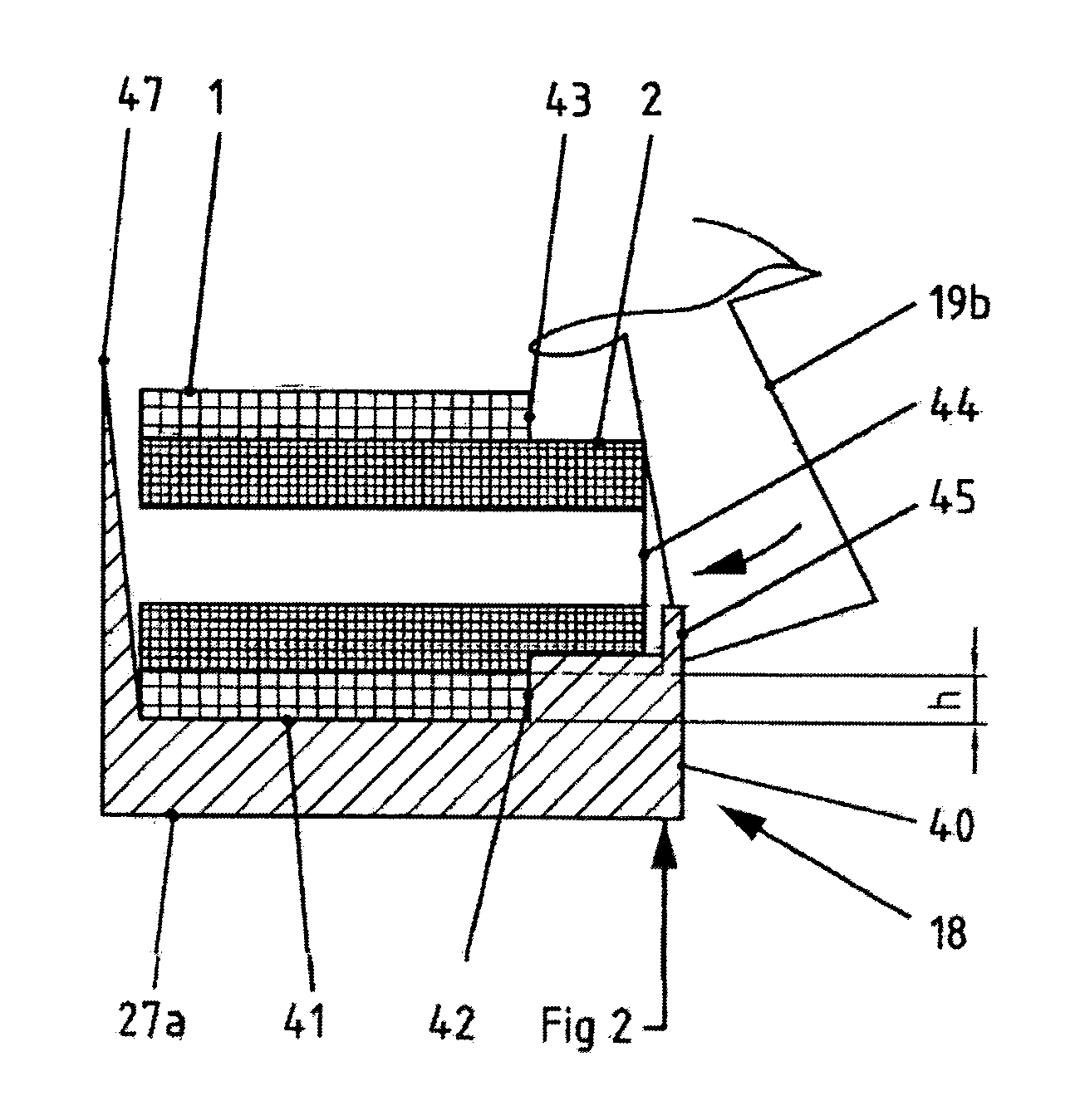
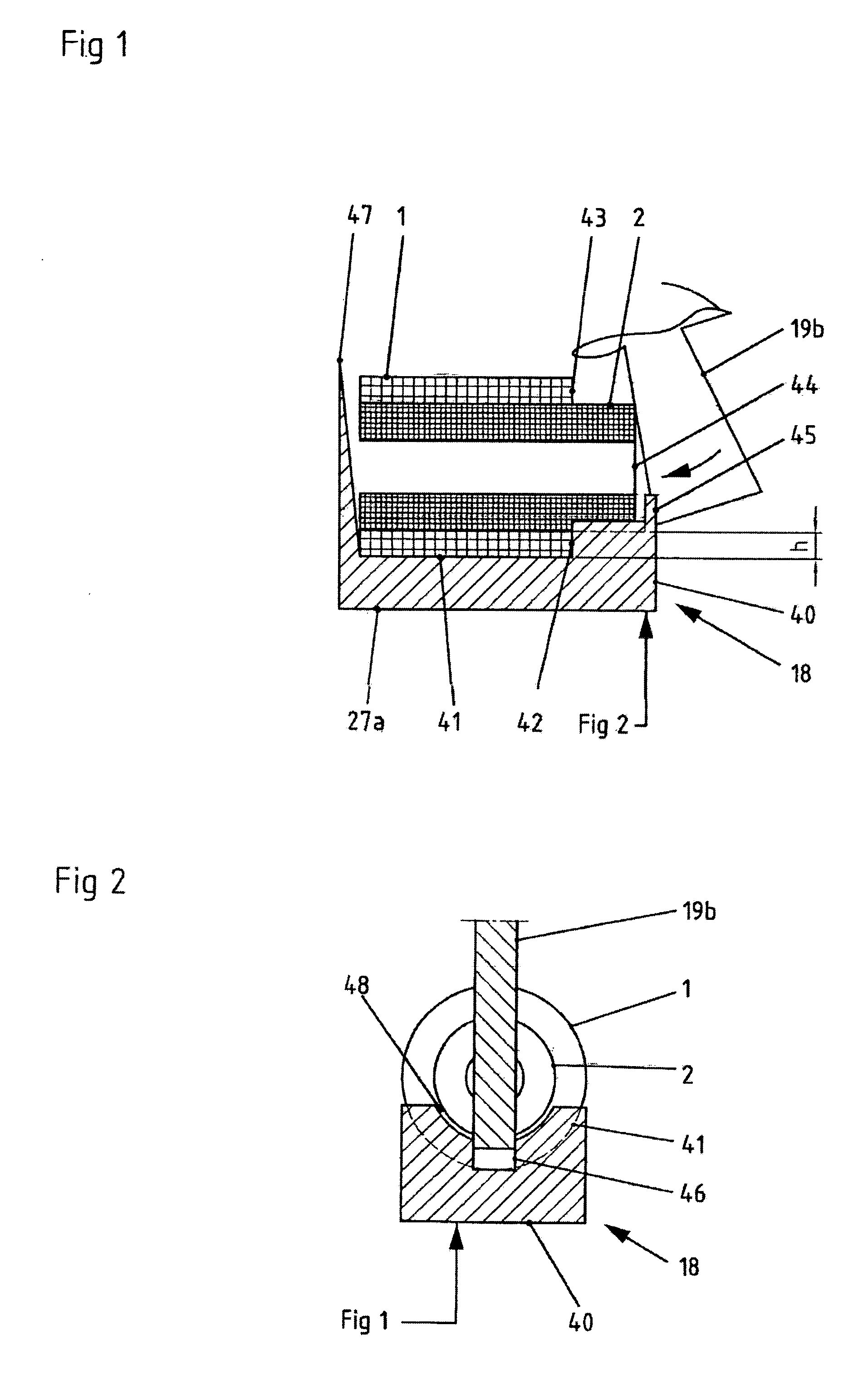
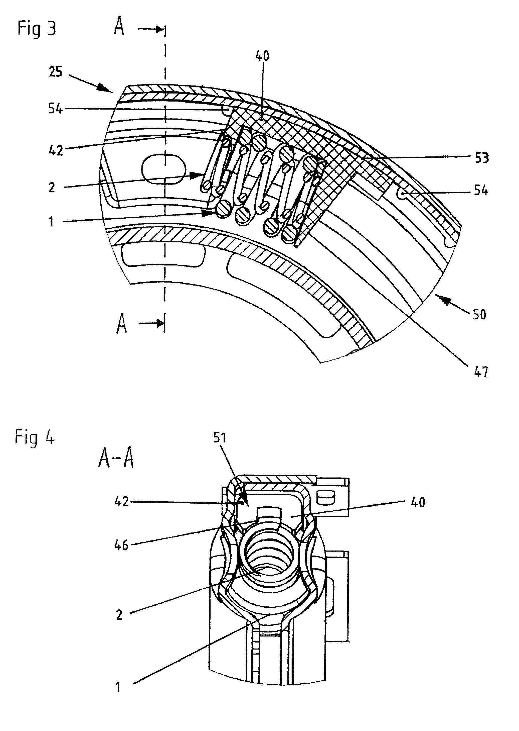
[0043]FIGS. 6 and 7 illustrate a torsional vibration damper 3 having a primary element in the form of a central disk 26 and having a secondary element in the form of two side disks 24, 25 which are rotationally fixedly connected to one another. Spring elements composed of a plurality of spring sets 5, 6, 7, 8, 9, 10, 11, 12, 13, 14, 15, 16 are arranged around the central disk 26 in a cavity formed by the rear side disk 24 and by the front side disk 25. In the present exemplary embodiment, each of the spring sets 5, 6, 7, 8, 9, 10, 11, 12, 13, 14, 15, 16 is composed of two helical springs situated one inside the other; a first, outer spring 1 and a second, inner spring 2. The spring sets 5, 6, 7, 8, 9, 10 and 11, 12, 13, 14, 15, 16 respectively are arranged in series, so as to form in each case one spring element, by means of spacers, so-called slide shoes 28, 29, 30, 31, 32 and 33, 34, 35, 36, 37 respectively. An end shoe 18a, 18b, 18c, 18d is arranged on the respective end of a spr...


PUM


Abstract

A shoe mounts an outer spring defining a longitudinal direction and an inner spring arranged within the outer spring. The outer and inner springs define corresponding end sides of the outer and inner springs, and the shoe defines an end side of the shoe. A spring-position limitation limits the outer spring in its longitudinal direction and enables the inner spring to emerge at the end side of the shoe out of the outer spring. A driver primary element exerts a pressure on the inner spring as the driver approaches the outer and inner springs in a direction of the corresponding end sides of the outer and inner springs.

Description

CROSS-REFERENCE TO RELATED APPLICATIONS[0001]This application claims benefit of PCT Patent Application PCT / EP2008 / 003300 entitled “SHOE HAVING A SPRING POSITION LIMITATION, OR TORSIONAL OSCILLATION DAMPER HAVING SUCH A SHOE” and filed on Apr. 24, 2008, which claims benefit of German Patent Application 10 2007 022 891.2 filed on May 14, 2007.BACKGROUND OF INVENTION[0002]1. Field of Invention[0003]The invention relates to a shoe having a spring-position limitation for use, in particular, in a torsional-vibration damper and to a torsional-vibration damper having end shoes and / or slide shoes designed on the basis of such shoe.[0004]2. Description of Related Art[0005]EP 1 584 839 A1 discloses a torsional vibration damper having a drive-input-side primary element which has at least one primary driver and having a drive-output-side secondary element which has at least one secondary driver, which primary element and secondary element can be rotated relative to one another about a neutral po...

Claims


Application Information

Patent Timeline
Patent Type & Authority Applications(United States)
IPC IPC(8): F16F15/134F16D47/02
CPCF16F15/13438F16F15/13461F16F15/13453
Inventor BOELLING, JOCHEN
Owner BORGWARNER INC
Why Eureka
Try Eureka