Hydraulic valve, a hybrid helicopter provided with such a hydraulic valve, and a method implemented by the hydraulic valve

a technology of hydraulic valve and hybrid helicopter, which is applied in the direction of propellers, aircraft transmission means, water-acting propulsive elements, etc., can solve the problems of non-negligible head loss, affecting the reaction time of the device between the first moment when the pilot gives an order and the second moment when the order is accomplished, and the sliding of the associated hydraulic valve to mov

Inactive Publication Date: 2010-06-03
EUROCOPTER
View PDF17 Cites 4 Cited by
  • Summary
  • Abstract
  • Description
  • Claims
  • Application Information

AI Technical Summary

Benefits of technology

[0028]An aspect of the present invention is thus to propose a hydraulic valve provided with a control rod and an outlet rod suitable for controlling a servocontrol of a hybrid helicopter while also enabling a pilot to be aware that the control linkage going from the pilot's control means to the propeller blades is operating properly, even though the assembly comprising the hydraulic valve and the servocontrol has a reaction time that is not zero.

Problems solved by technology

Action taken on the flight controls causes the control rod to move, and consequently causes the slide of the associated hydraulic valve to move.
Nevertheless, it should be observed that the distance between the hydraulic valve and the servocontrol is considerable, thereby giving rise to a non-negligible amount of head loss.
Thus, the reaction time of the device between a first moment when the pilot gives an order and a second moment when the order has been accomplished is relatively long.
Unfortunately, in order to counter a gust of wind, or in order to avoid an obstacle, the pilot might impart fast movement to the pedals over a large amplitude.
Since the pilot does not see the aircraft respond there is a danger of the pilot wondering whether operation is still normal, or whether the flight control is faulty.
This leads to a problematic situation in which the pilot might start performing actions that ought not to be performed, e.g. by giving an order contrary to the initial order.
Nevertheless, that factor appears to be insufficient insofar as the amplitude of the movement can also have an impact.

Method used


Image

  • Hydraulic valve, a hybrid helicopter provided with such a hydraulic valve, and a method  implemented by the hydraulic valve
  • Hydraulic valve, a hybrid helicopter provided with such a hydraulic valve, and a method  implemented by the hydraulic valve
  • Hydraulic valve, a hybrid helicopter provided with such a hydraulic valve, and a method  implemented by the hydraulic valve

Examples


Embodiment Construction

[0078]Elements that are present in more than one of the figures are given the same references in each of them.

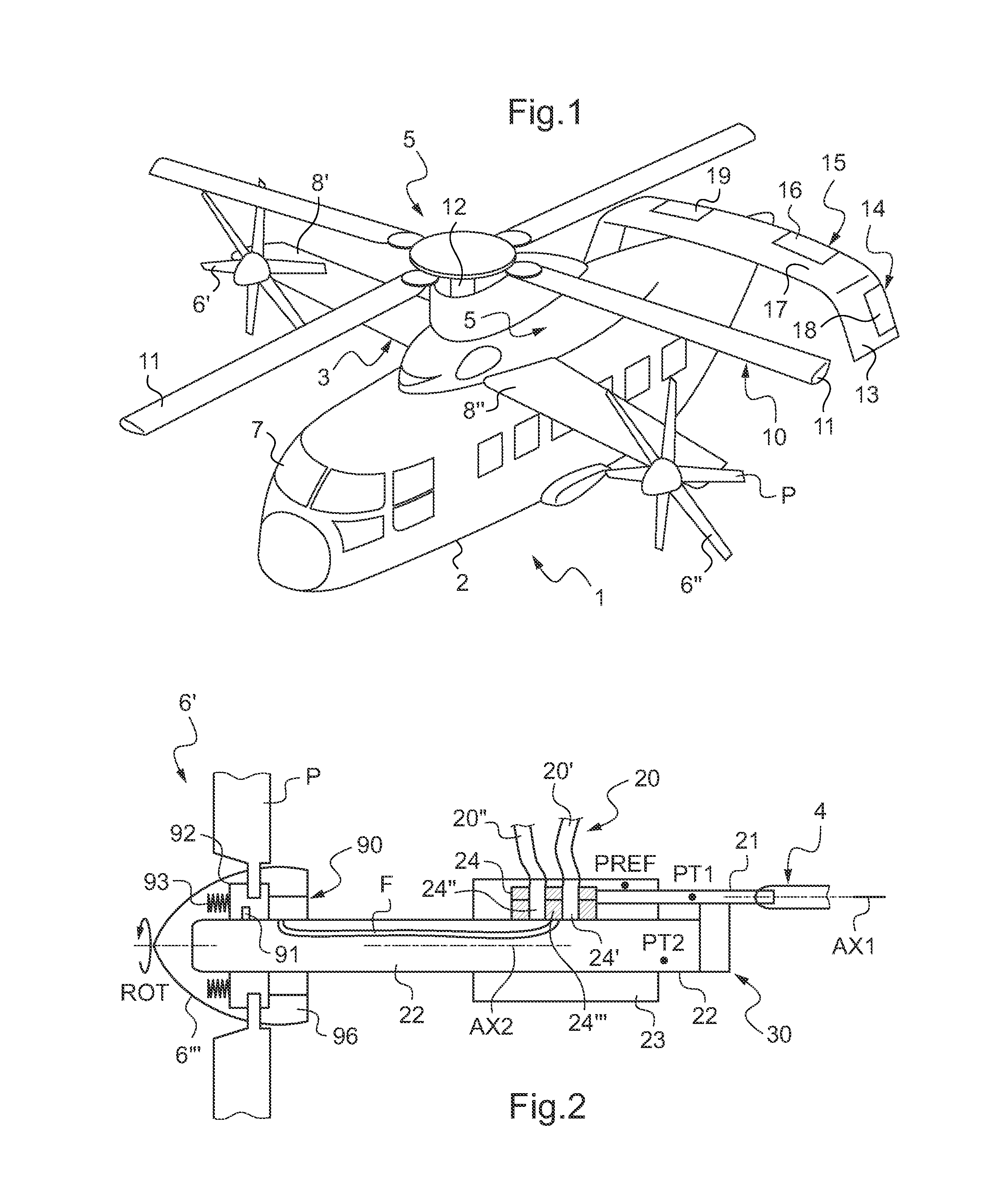
[0079]FIG. 1 shows a hybrid helicopter 1 comprising a fuselage 2 with a cockpit 7 at the front thereof, a rotary wing provided with at least one rotor 10 for driving blades 11 in rotation firstly by means of two turbine engines 5 disposed on top of the fuselage 2, on either side of a longitudinal plane of symmetry of the rotorcraft, and secondly by means of a first main gearbox (MGB) not shown in FIG. 1.

[0080]It should be observed that the two turbine engines 5 are not visible in FIG. 1 because of the presence of fairings. Furthermore, the hybrid helicopter 1 is provided with a high wing 3 made up of two half-wings 8′ and 8″ located at the top of the fuselage 2. The hybrid helicopter 1 is propelled by first and second propellers 6′ and 6″ driven by the two turbine engines 5, one of the propellers 6′ and 6″ being located at each of the outer ends of the wing 3.

[0081]Furthermo...


PUM


Abstract

A hydraulic valve assembly includes a hydraulic valve, a control rod configured to be moved in translation along a first longitudinal axis by flight controls of an aircraft, a servocontrol, and an outlet rod configured to be moved in translation along a second longitudinal axis and configured to transfer a hydraulic fluid between the servocontrol and the hydraulic valve. A blocker device is configured to block a movement of the control rod when a difference between a first movement of the control rod and a second movement of the outlet rod exceeds a predetermined threshold and includes at least one moveable abutment configured to block the movement of the control rod when the predetermined threshold is reached and configured to move in longitudinal translation with the outlet rod, and a differential lever configured to mechanically link the control rod to the outlet rod and to cooperate with the at least one moveable abutment.

Description

[0001]Priority is claimed to French Application No. 08 06735, filed Dec. 1, 2008, the entire disclosure of which is incorporated by reference herein.[0002]The present invention relates to a hydraulic valve, to a hybrid helicopter provided with such a hydraulic valve, and to a method implemented by the hydraulic valve. More particularly, the invention relates to a hybrid helicopter relating to an advanced concept of a vertical takeoff and landing aircraft “VTOL aircraft”.[0003]This advanced hybrid helicopter concept combines at reasonable expense the efficiency in vertical flight of a conventional helicopter with the high travel speed performance made possible by using propulsive propellers and installing modern turbine engines.BACKGROUND[0004]In order to thoroughly understand the purpose of the invention, it is appropriate to consider the main kinds of flying machine that correspond to airplanes and to rotorcraft. The term “rotorcraft” covers any aircraft in which lift is provided i...

Claims


Application Information

Patent Timeline
Patent Type & Authority Applications(United States)
IPC IPC(8): B64C27/26F16K35/00F15D1/00
CPCB64C11/38B64C27/22B64C13/40Y10T137/0318
Inventor JALAGUIER, JEAN-PIERRE
Owner EUROCOPTER
Why Eureka
Try Eureka