Shift register apparatus

Active Publication Date: 2010-06-03
AU OPTRONICS CORP
View PDF9 Cites 29 Cited by
  • Summary
  • Abstract
  • Description
  • Claims
  • Application Information

AI Technical Summary

Benefits of technology

[0008]The present invention is directed to a shift register apparatus with bot

Problems solved by technology

However, the stability of the output signals (i.e. the scan signal) of the circuits in the conventional a-Si shift registers is not good; and it is easily influenced by the coupling of the external clock signals to produce the large noise (it can be understood the coupling noise), thereby causing the wrong log

Method used


Image

  • Shift register apparatus
  • Shift register apparatus
  • Shift register apparatus

Examples


Embodiment Construction

[0031]Reference will now be made in detail to the present preferred embodiments of the invention, examples of which are illustrated in the accompanying drawings. Wherever possible, the same reference numbers are used in the drawings and the description to refer to the same or like parts.

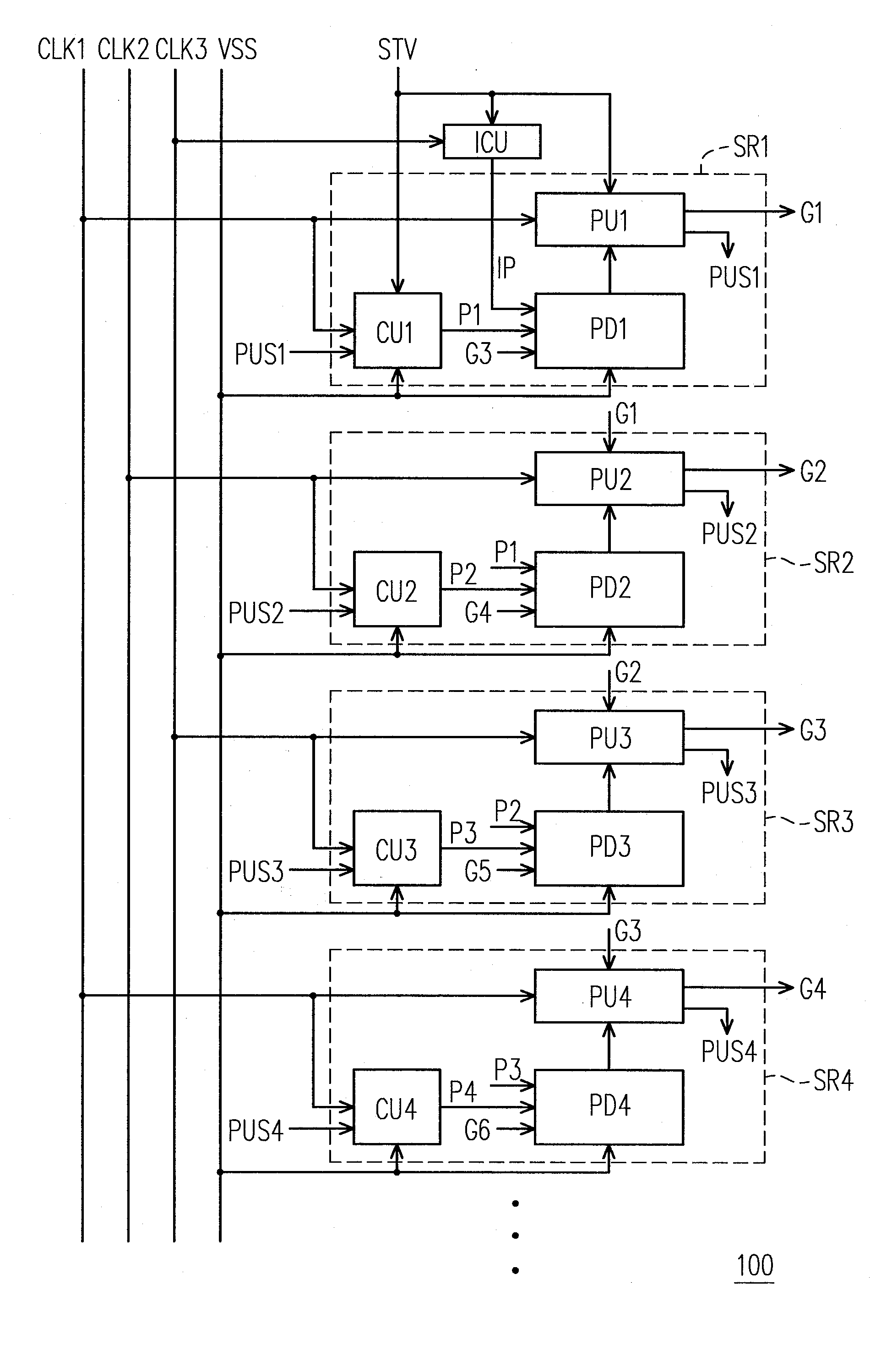
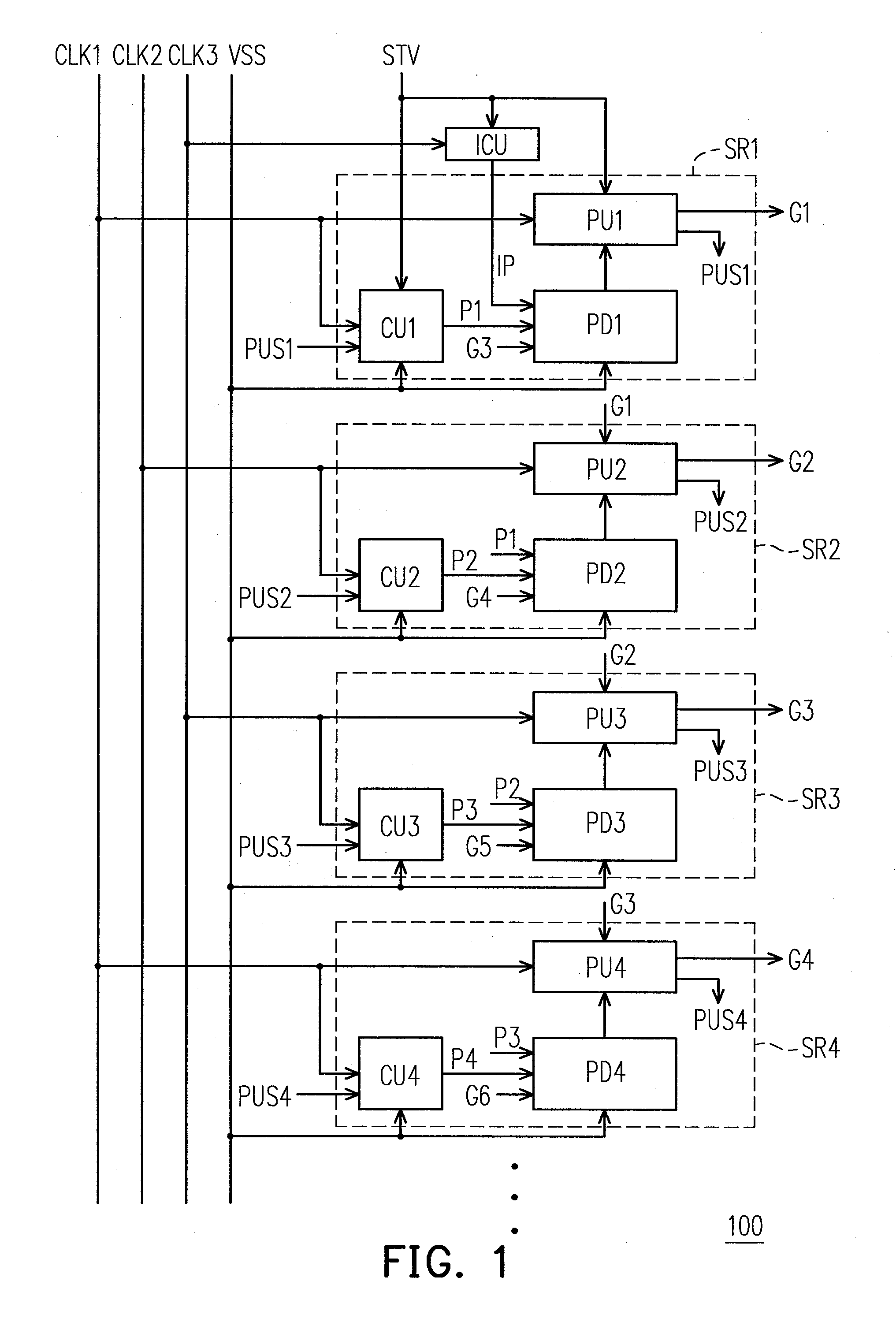
[0032]FIG. 1 is a block diagram of a shift register apparatus 100 according to an exemplary embodiment of the present invention. Referring to FIG. 1, the shift register apparatus 100 includes a plurality of shift registers SR1˜SRn connected in series (FIG. 1 shows only four shift registers SR1˜SR4 for explaining), and each of the shift registers SR1˜SR4 includes a pull-up unit, a control unit and a pull-down unit respectively, namely, the shift register SR1 includes the pull-up unit PU1, the control unit CU1 and the pull-down unit PD1; the shift register SR2 includes the pull-up unit PU2, the control unit CU2 and the pull-down unit PD2; the shift register SR3 includes the pull-up unit PU3, the contro...


PUM


Abstract

A shift register apparatus is provided. The pull-down unit of each of the shift registers in the shift register apparatus is controlled by itself, previous, and next two shift registers to enhance the ability of pull-down and voltage regulating. Therefore, the circuit structure of each of the shift registers does not need to be designed a large compensation capacitor therein to substantially restrain the coupling noise effect caused by the clock signal, and thus permitting that each of the shift registers can be collocated with a small compensation capacitor to enhance the output capability thereof.

Description

CROSS-REFERENCE TO RELATED APPLICATION[0001]This application claims the priority benefit of Taiwan application serial no. 97146618, filed on Dec. 1, 2008. The entirety of the above-mentioned patent application is hereby incorporated by reference herein and made a part of this specification.BACKGROUND OF THE INVENTION[0002]1. Field of the Invention[0003]The present invention relates to a shift register apparatus, more particularly, to a shifter register apparatus capable of restraining the coupling noise.[0004]2. Description of the Related Art[0005]In recent years, with great advance in the fabricating techniques of opto-electronics and semiconductor devices, flat panel displays (FPDs) have been vigorously developed. Among the FPDs, a liquid crystal display (hereinafter “LCD”) has become the mainstream display product due to its advantages of outstanding space utilization efficiency, low power consumption, free radiation, and low electrical field interference. Accordingly, the LCD de...

Claims


Application Information

Patent Timeline
IPC IPC(8): G11C19/28
CPCG11C19/28
Inventor LIAO, YI-SUEICHEN, CHIEN-LIANGCHIU, CHEN-LUNLEE, HAO-CHIEHCHEN, KUAN-YU
Owner AU OPTRONICS CORP
Why Eureka
Try Eureka