Biaxial Laser Anemometry Probe

a laser anemometer and biaxial probe technology, applied in the field of laser anemometers, can solve the problems of increasing the risk of failure of certain elements, high cost of combining two mono-axial probes to form a bi-axial probe, and almost impossible to directly obtain the relative speed vector in relation to the air, etc., to achieve the effect of low cost and large-scale production

Active Publication Date: 2010-06-03
THALES SA
View PDF2 Cites 7 Cited by
  • Summary
  • Abstract
  • Description
  • Claims
  • Application Information

AI Technical Summary

Benefits of technology

[0026]The use of the integrated optical technology consisting in etching the op

Problems solved by technology

The local angles of incidence and of sideslip of an aircraft can vary strongly, so it is almost impossible to directly obtain the norm of the relative speed vector in re

Method used


Image

  • Biaxial Laser Anemometry Probe
  • Biaxial Laser Anemometry Probe
  • Biaxial Laser Anemometry Probe

Examples


Embodiment Construction

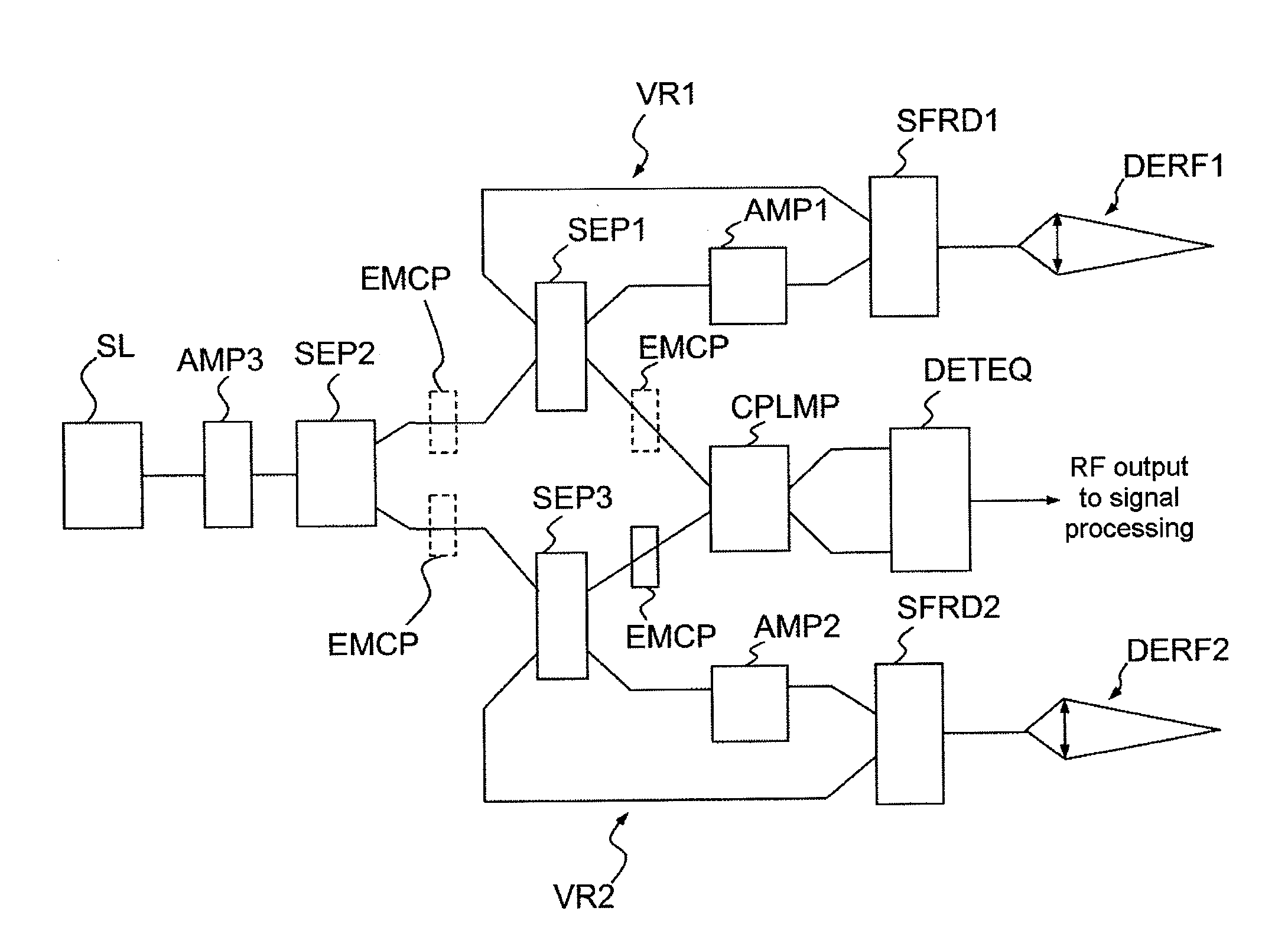
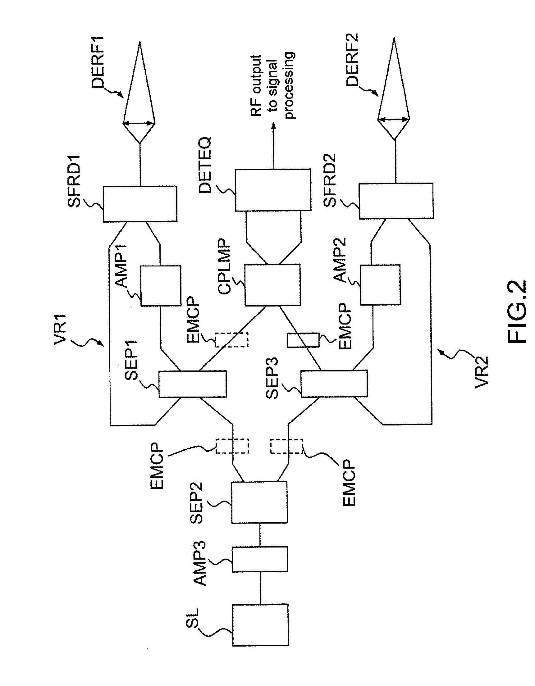
[0032]As illustrated in FIG. 2, a biaxial laser anemometry probe comprises a laser source SL supplying a linearly polarized reference wave, a first separator SEP1 separating the signal originating from the laser source SL into a signal transmitted to a first amplifier AMP1 and a signal transmitted to a coupler with maintained polarization CPLMP.

[0033]The biaxial laser anemometry probe also comprises a first device DERF1 for transmitting / receiving beams in a first direction, or, in a slight misuse of language, along a first axis, and a first backscattered beam separator SFRD1 arranged between the first amplifier AMP1 and the first transmitter / receiver device DERF1.

[0034]The biaxial laser anemometry probe is also provided with a second device DERF2 for transmitting / receiving beams in a second direction distinct from the first direction, or, in a slight misuse of language, along a second axis distinct or of different direction from the first axis, and with a second backscattered beam s...


PUM


Abstract

The subject of the present invention is a laser anemometry probe for optical homodyne detection of frequency offset by Doppler effect, comprising two devices (DERF1, DERF2) for transmitting/receiving beams in two different directions, avoiding duplicating a plurality of elements of a mono-axial laser anemometry probe.

Description

CROSS-REFERENCE TO RELATED APPLICATIONS[0001]This application claims priority of foreign French patent application no. FR 0806767, filed Dec. 2, 2008, the disclosure of which is hereby incorporated by reference in its entirety.BACKGROUND OF THE INVENTION[0002]The present invention relates to a laser anemometry probe for optical homodyne detection of frequency offset by Doppler effect.[0003]Mono-axial laser anemometry probes are known that are used to measure aircraft speeds relative to the surrounding environment.[0004]This type of probe is based on a technique consisting in measuring the frequency offset, representative of the relative speed in relation to the air, between a laser beam emitted into the atmosphere and the beam backscattered by the natural aerosols in the air, used as wind field tracers. The expression longitudinal Doppler laser anemometry is used because the frequency offset that results from the Doppler effect is directly proportional to the projection of the speed...

Claims


Application Information

Patent Timeline
IPC IPC(8): G01P3/36G01B9/02B44C1/22G01S17/87
CPCG01P5/26G01S17/87G01S17/58G01S7/499
Inventor RODEAU, PHILIPPESCHLOTTERBECK, JEAN-PIERRE
Owner THALES SA
Why Eureka
Try Eureka