Active Thermal Runaway Mitigation System for Use Within a Battery Pack

a technology of active thermal runaway and battery pack, which is applied in the field of battery packs, can solve the problems of secondary cells that often require special handling during fabrication, battery type is not without its drawbacks, and secondary cells are not without their drawbacks, so as to prevent the propagation of thermal runaway events, minimize personnel hazards, and mitigate the effect of a single cell undergoing

Active Publication Date: 2010-06-03
TESLA INC
View PDF14 Cites 162 Cited by
  • Summary
  • Abstract
  • Description
  • Claims
  • Application Information

AI Technical Summary

Benefits of technology

[0007]An active thermal runaway mitigation system is provided that mitigates the effects of a single cell undergoing thermal runaway, thereby preventing the propagation of the thermal runaway event to neighboring cells within the battery pack. As a result, battery pack damage as well as collateral damage and personnel hazards are minimized.

Problems solved by technology

Although rechargeable batteries offer a number of advantages over disposable batteries, this type of battery is not without its drawbacks.
In general, most of the disadvantages associated with rechargeable batteries are due to the battery chemistries employed, as these chemistries tend to be less stable than those used in primary cells.
Due to these relatively unstable chemistries, secondary cells often require special handling during fabrication.
Additionally, secondary cells such as lithium-ion cells tend to be more prone to thermal runaway than primary cells, thermal runaway occurring when the internal reaction rate increases to the point that more heat is being generated than can be withdrawn, leading to a further increase in both reaction rate and heat generation.
Thermal runaway may be initiated by a short circuit within the cell, improper cell use, physical abuse, manufacturing defects, or exposure of the cell to extreme external temperatures.
As a result, power from the battery pack is interrupted and the system employing the battery pack is more likely to incur extensive collateral damage due to the scale of thermal runaway and the associated release of thermal energy.

Method used


Image

  • Active Thermal Runaway Mitigation System for Use Within a Battery Pack
  • Active Thermal Runaway Mitigation System for Use Within a Battery Pack
  • Active Thermal Runaway Mitigation System for Use Within a Battery Pack

Examples


Embodiment Construction

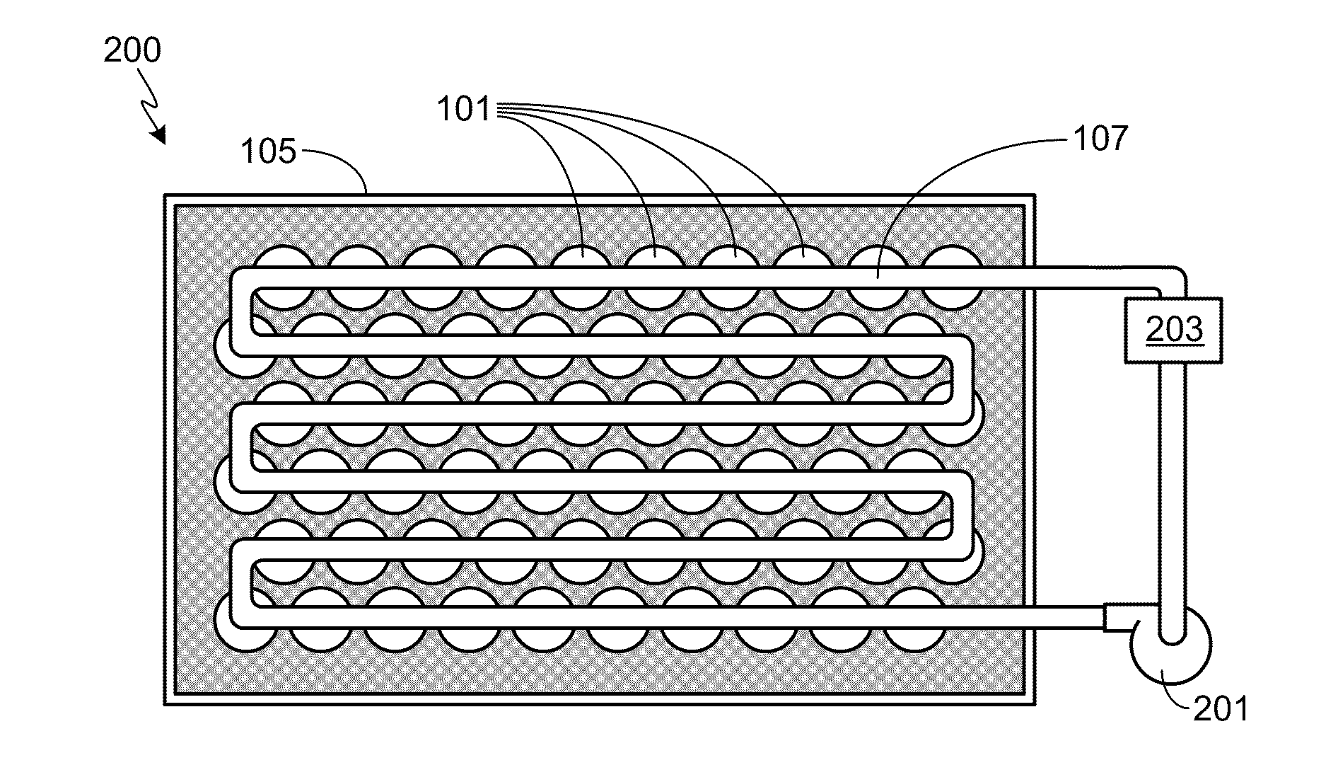
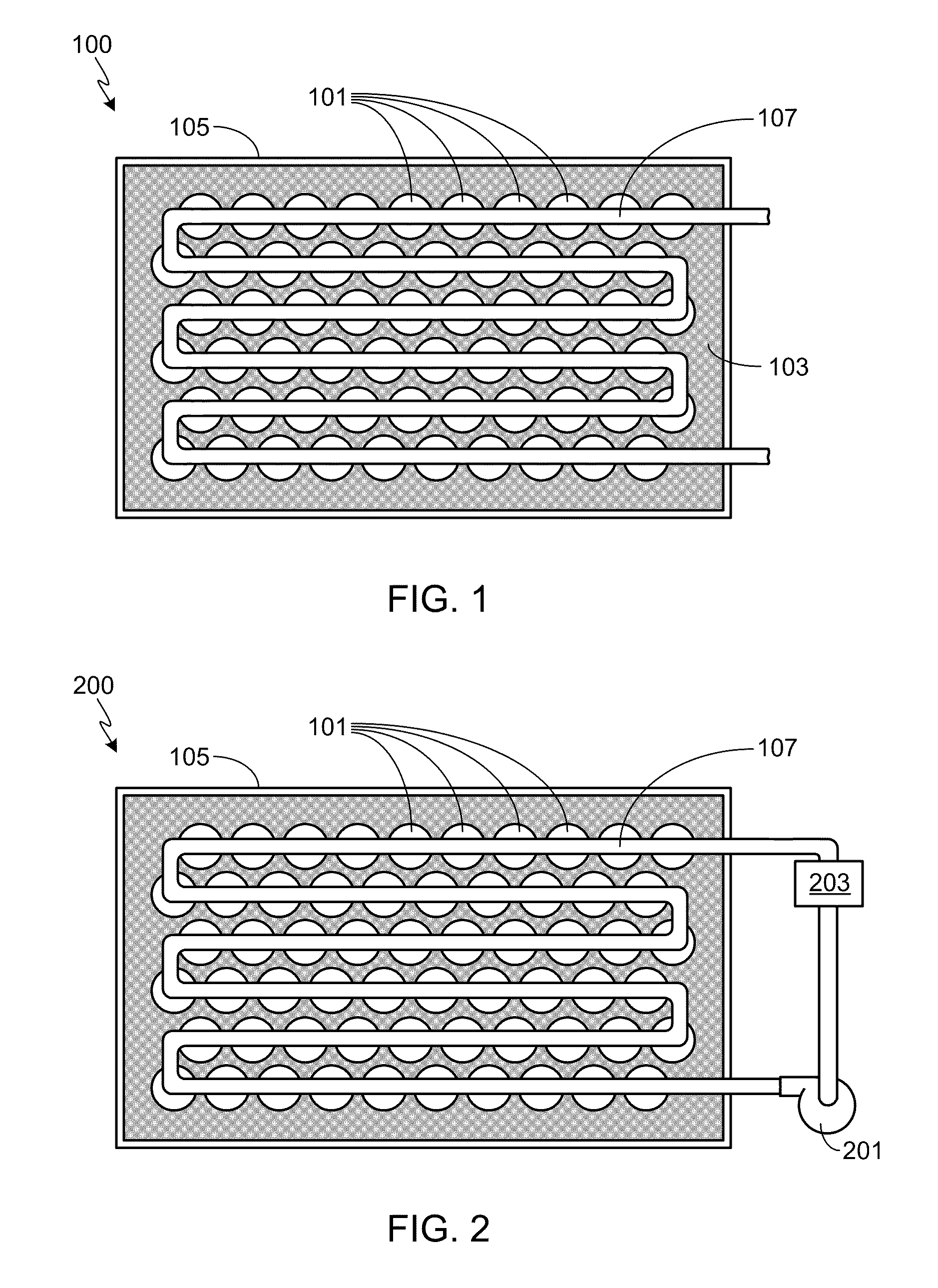
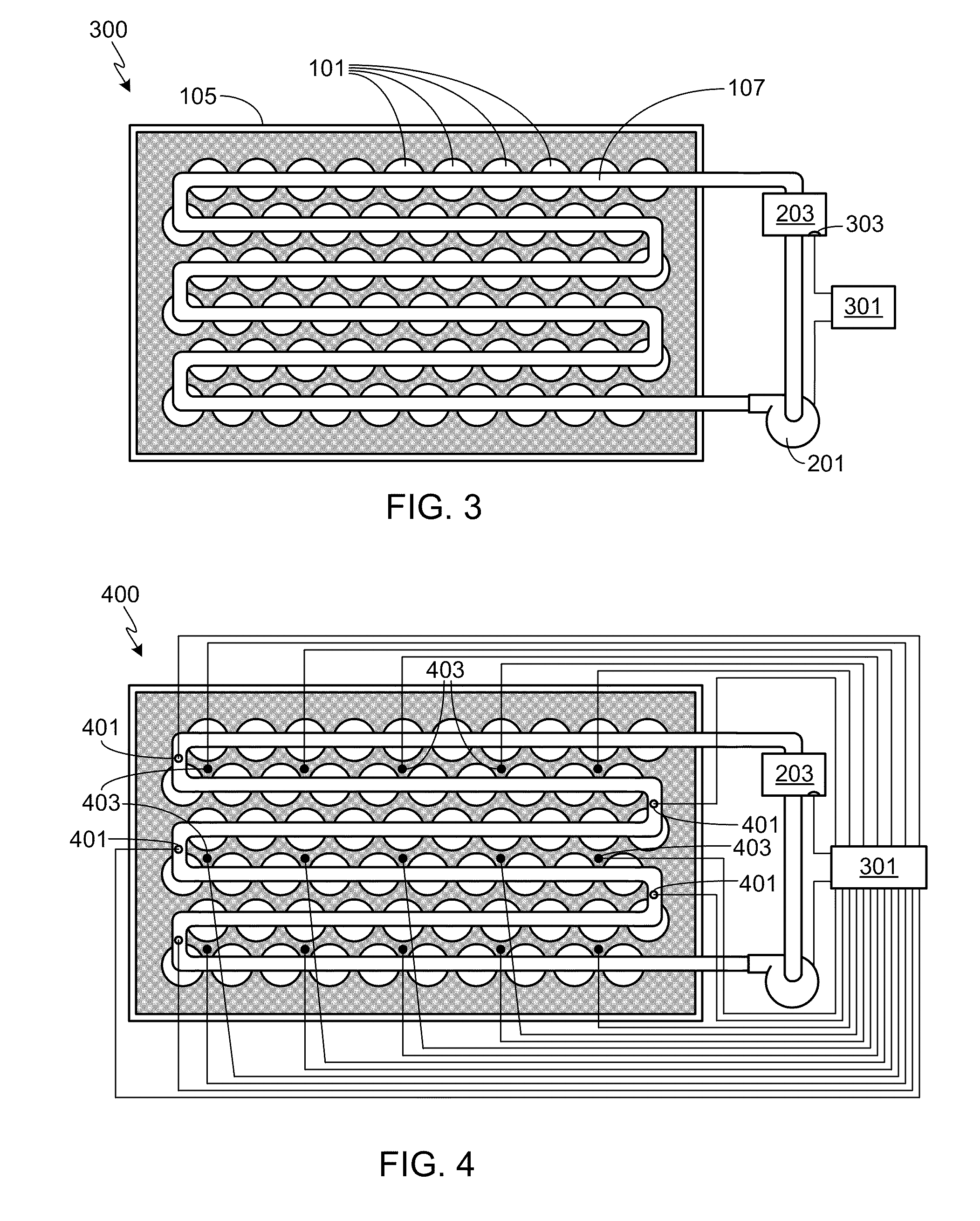
[0029]In the following text, the terms “battery”, “cell”, and “battery cell” may be used interchangeably and may refer to any of a variety of different cell chemistries and configurations including, but not limited to, lithium ion (e.g., lithium iron phosphate, lithium cobalt oxide, other lithium metal oxides, etc.), lithium ion polymer, nickel metal hydride, nickel cadmium, nickel hydrogen, nickel zinc, silver zinc, or other battery type / configuration. The term “battery pack” as used herein refers to multiple individual batteries contained within a single piece or multi-piece housing, the individual batteries electrically interconnected to achieve the desired voltage and capacity for a particular application. It should be understood that identical element symbols used on multiple figures refer to the same component, or components of equal functionality. Additionally, the accompanying figures are only meant to illustrate, not limit, the scope of the invention and should not be consi...


PUM

PropertyMeasurementUnit
temperatureaaaaaaaaaa
melting temperatureaaaaaaaaaa

Abstract

An active thermal runaway mitigation system is provided that mitigates the effects of a single cell undergoing thermal runaway, thereby preventing the propagation of the thermal runaway event to neighboring cells within the battery pack. The provided system includes at least one, fluid-containing conduit in proximity to the cells within the battery pack. The conduit includes a plurality of breach points in proximity to the subset of cells, where each breach point is configured to form a breach at a preset temperature that is lower than the melting temperature of the conduit. Once a breach is formed, the fluid contained within the conduit is discharged through the breach.

Description

FIELD OF THE INVENTION[0001]The present invention relates generally to batteries, and more particularly, to a means for mitigating the effects of thermal runaway within a battery pack.BACKGROUND OF THE INVENTION[0002]Batteries can be broadly classified into primary and secondary batteries. Primary batteries, also referred to as disposable batteries, are intended to be used until depleted, after which they are simply replaced with one or more new batteries. Secondary batteries, more commonly referred to as rechargeable batteries, are capable of being repeatedly recharged and reused, therefore offering economic, environmental and ease-of-use benefits compared to disposable batteries.[0003]Although rechargeable batteries offer a number of advantages over disposable batteries, this type of battery is not without its drawbacks. In general, most of the disadvantages associated with rechargeable batteries are due to the battery chemistries employed, as these chemistries tend to be less sta...

Claims


Application Information

Patent Timeline
Patent Type & Authority Applications(United States)
IPC IPC(8): H01M10/50
CPCH01M10/5004H01M10/5016H01M10/502H01M10/503G05D23/123H01M10/5073H01M10/5075H01M10/5089H01M10/5069H01M10/625H01M10/63H01M10/6567H01M10/643H01M10/6564H01M10/6566H01M10/659H01M10/613Y02E60/10H01M50/609H01M2200/10
Inventor PRILUTSKY, ALEXHERMANN, WESTON ARTHUR
Owner TESLA INC
Why Eureka
Try Eureka