
Secondary battery and method for producing the same

Inactive Publication Date: 2010-06-03
PANASONIC CORP
View PDF2 Cites 17 Cited by
  • Summary
  • Abstract
  • Description
  • Claims
  • Application Information

AI Technical Summary

Benefits of technology

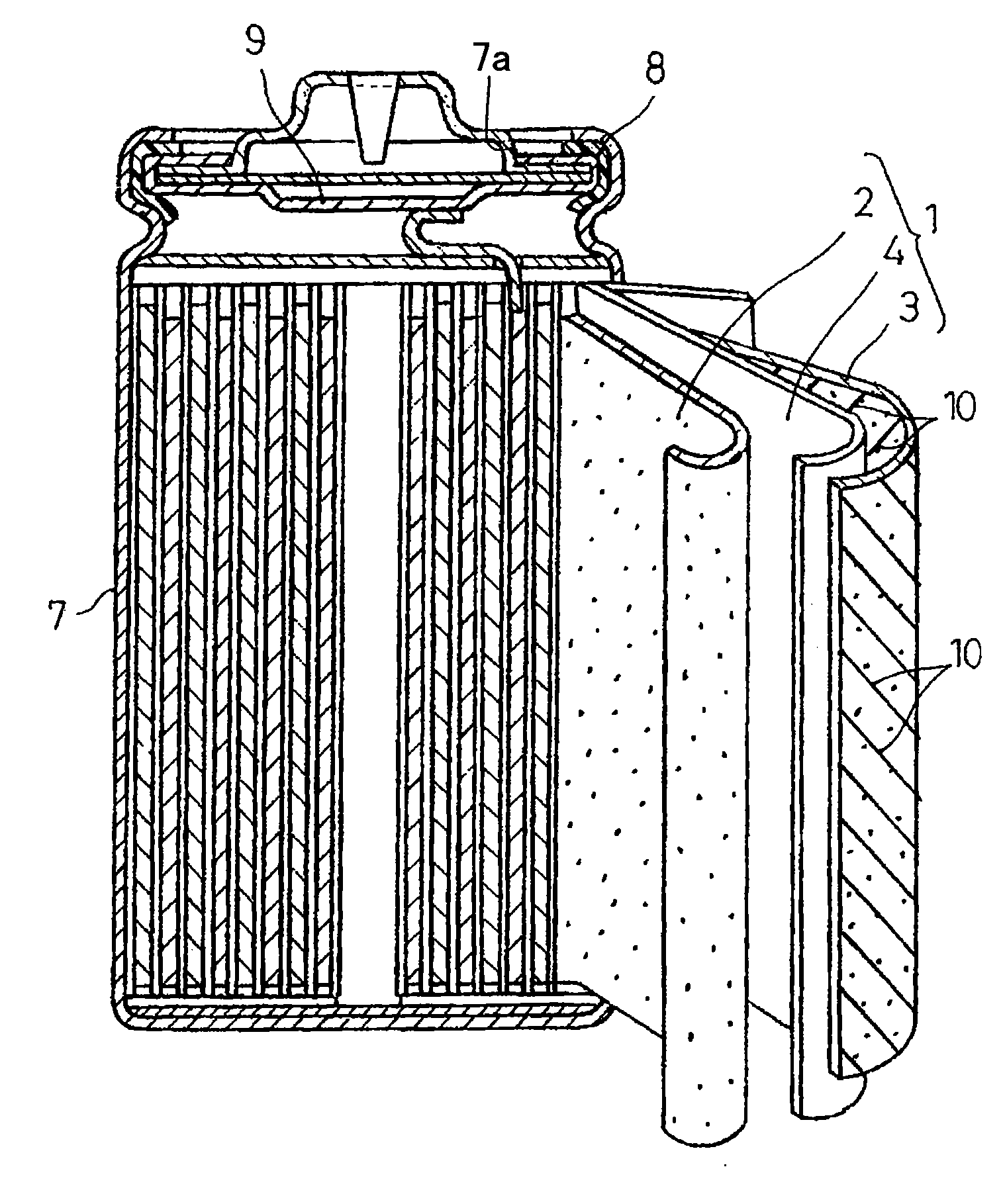
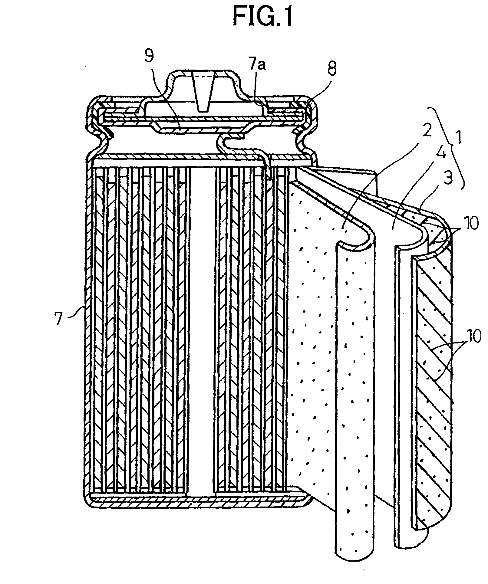
[0043]According to the present disclosure, a secondary battery allows improvement of the electrolyte injection property and impregnation in the electrolyte injection step resulting in high yield production of the secondary battery, and also can achieve safety with which the occurrence of an internal short-circuit and the like can be effectively prevented.

Problems solved by technology

When an external physical impact is added to a lithium secondary battery by error for some reason, or when a lithium secondary battery is charged with an excessively large current, damage to a separator in the battery and the like might be caused to bring a positive electrode plate and a negative electrode plate in contact with each other, and thus an internal short-circuit might occur.
When such an internal short-circuit occurs, a current flows intensively at short-circuited part and, as a result, heat is generated.
If a large amount of heat is generated due to the internal short-circuit, materials forming the positive electrode and the negative electrode might be decomposed, an electrolyte might be caused to boil, and gas might be generated due to the decomposition of materials forming the positive electrode and the negative electrode.
However, as in this method, when a filling density of an active material in each of the electrode plates is increased, a porosity in each of the electrode plates is reduced and it becomes difficult to impregnate of an electrolyte in each of the electrode plates.
Accordingly, impregnation of the electrolyte into an electrode plate group is dramatically reduced, thus resulting in undesirable nonuniform distribution of the electrolyte in the electrode plate group.

Method used


Image

  • Secondary battery and method for producing the same
  • Secondary battery and method for producing the same
  • Secondary battery and method for producing the same

Examples


example 1

[0113]Hereinafter, examples of the present disclosure will be described.

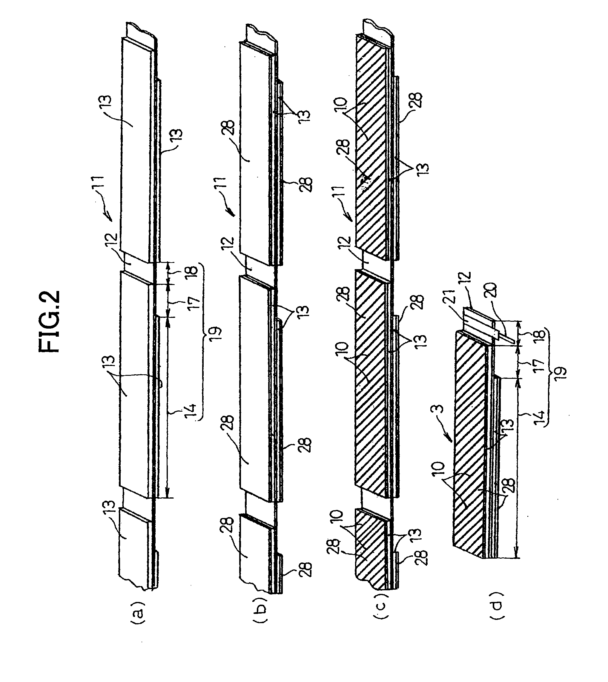
[0114]One hundred parts by weight of artificial graphite as a negative electrode active material, 2.5 parts by weight (1 part by weight in terms of solid content of a binder) of styrene butadiene copolymer rubber particle dispersing element (40 wt % of solid content) as a binder, 1 part by weight of carboxymethylcellulose as a thickener were stirred with an adequate amount of water by a blender, thereby forming a negative electrode mixture paste. The negative electrode mixture paste was applied to a current collector core material 12 of a copper foil having a thickness of 10 μm, and dried to form a negative electrode active material layer 13, and the negative electrode active material layer13 was compressed by roll pressing so as to have a total thickness of about 200 μm. Next, a small amount of a binder was added to alumina oxide particles having a particle size of about 1.2 μm and then mixed, thereby forming i...


PUM

PropertyMeasurementUnit
Fractionaaaaaaaaaa
Fractionaaaaaaaaaa
Thicknessaaaaaaaaaa

Abstract

A secondary battery includes an electrode plate group (1) in which a positive electrode plate (2) and a negative electrode plate (3) are wound or stacked with a separator (4) interposed therebetween and a battery case (7) in which the electrode plate group (1) and an electrolyte are contained. At least one of the positive electrode plate (2) and the negative electrode plate (3) includes a porous protective film (28) formed on a surface of an active material layer. In a surface of the at least one of the electrode plates on which the porous protective film (28) is provided, a plurality of grooves (10) are formed, and the grooves (10) are also formed in the surface of the active material so that each of the grooves (10) extends from the surface of the porous protective film (28) to the surface of the active material layer.

Description

TECHNICAL FIELD[0001]The disclosure of the present invention relates to a secondary battery such as a lithium secondary battery which can be produced with high productivity and also can achieve increased safety with which the occurrence of an internal short-circuit and the like can be effectively prevented.BACKGROUND ART[0002]In recent years, lithium secondary batteries which have grown in use as power supplies for driving portable electronic devices, communication devices, and the like are configured as secondary batteries with a high potential and a high discharge capacity by using a carbonaceous material capable of inserting and extracting lithium for a negative electrode plate and, composite oxide such as LiCoO2 or the like of transition metal and lithium for an active material of a positive electrode plate. However, with recent increase in function of electronic devices and communication devices, increased demands have been placed on the safety of battery while the capacity of ...

Claims


Application Information

Patent Timeline
IPC IPC(8): H01M6/10H01M10/04H01M4/13H01M4/139H01M10/0566H01M10/0585H01M10/0587
CPCH01M10/0431Y02E60/122Y10T29/49112Y10T29/49108Y10T29/49115Y02E60/10Y02P70/50H01M10/052H01M4/80H01M10/0585
Inventor MIYAHISA, MASAHARUOHSAWA, YOSHIKIKUMAKIRI, HIDEYUKIKATO, SEIICHI
Owner PANASONIC CORP
Learn More