Tool for machining stone or concrete floors

Inactive Publication Date: 2010-06-03
HTC SWEDEN AB
View PDF4 Cites 17 Cited by
  • Summary
  • Abstract
  • Description
  • Claims
  • Application Information

AI Technical Summary

Benefits of technology

[0016]Providing the machining element in a tool for machining floors and road surfaces with a free machining end having a symmetrically blunt shape, i.e. with no sharp edge/-s in any direction, means that the machining element machines the floor and/or road surface similar to a mill or a crusher, and that the machining of the floor/road surface is performed independently of the direction of rotation of the tool. Furthermore, a blunt shape is less sensible for strikes against projections, irregularities, e

Problems solved by technology

A disadvantage of known tools for machining of floor surfaces is that one and the same tool can not be used for carrier discs rotating in different directions when driven, whereby left hand and right hand versions of the tools have to be manufactured.
These left hand and right hand tool versions also have a disadvantage in that a left hand tool may not be mounted instead of a right hand tool or vice versa, whereby the risk of mistakes when mounting the tools increases.
Moreover, another di

Method used


Image

  • Tool for machining stone or concrete floors
  • Tool for machining stone or concrete floors
  • Tool for machining stone or concrete floors

Examples


Embodiment Construction

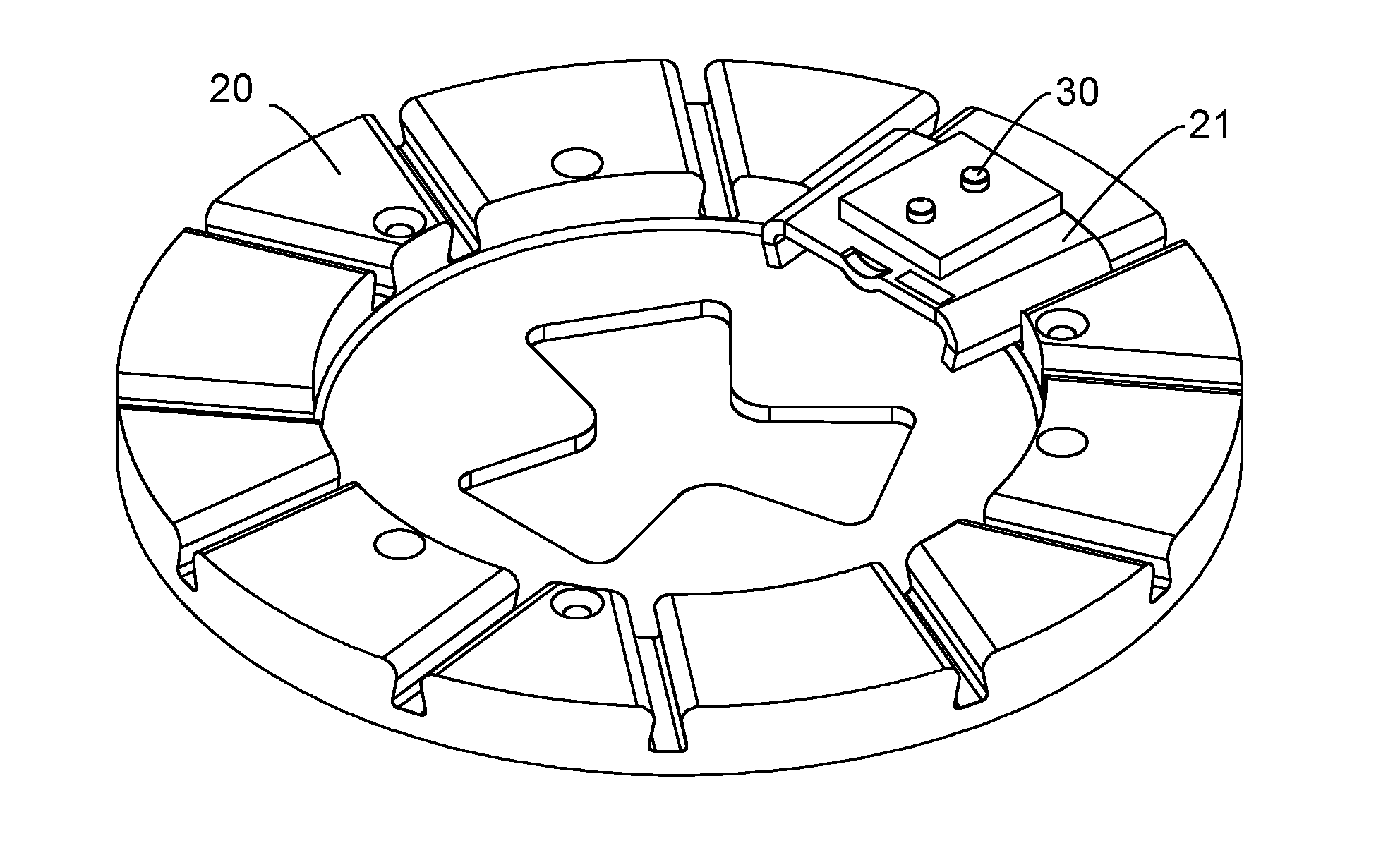
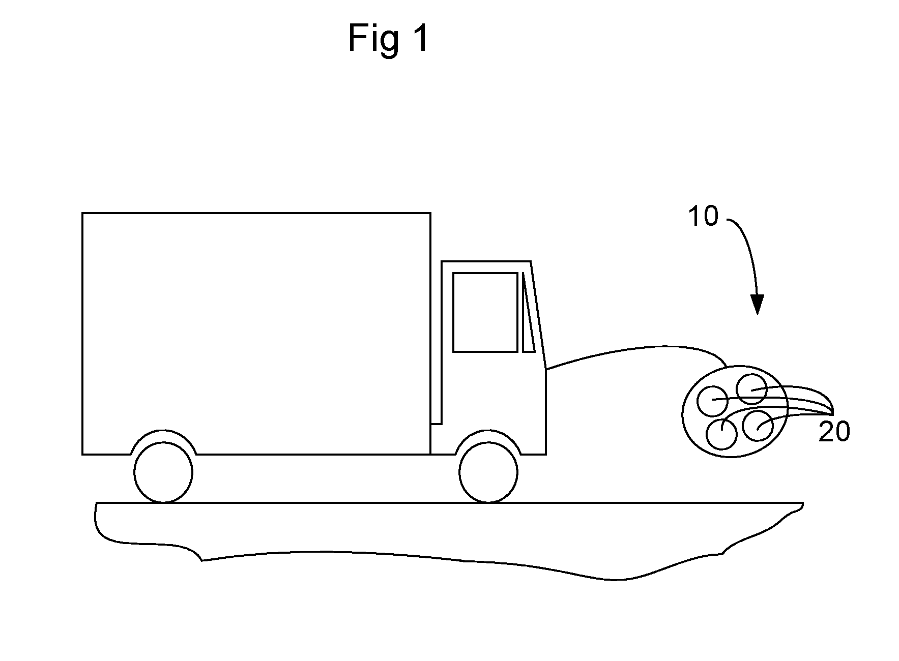
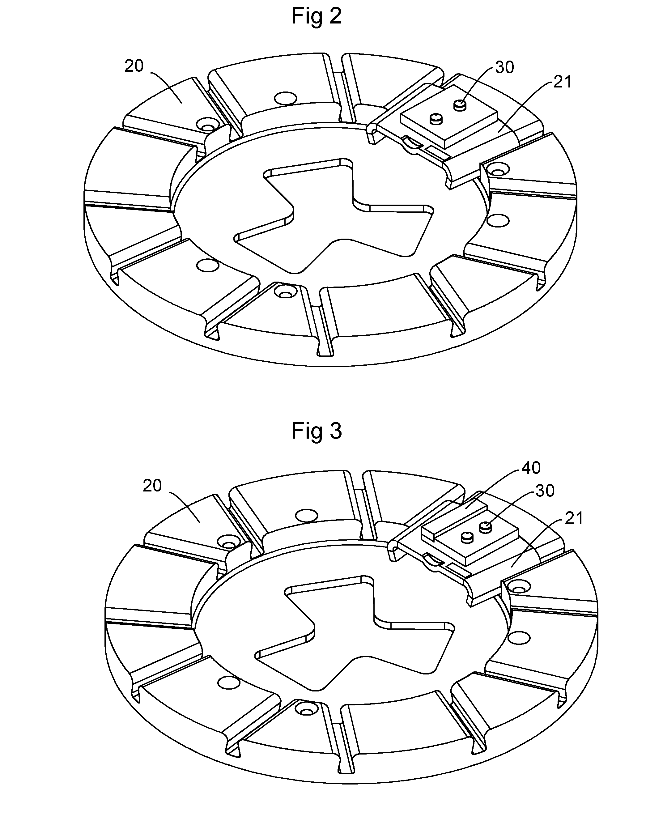
[0022]FIG. 1 indicates a machine for machining surfaces on floors and roads with an abrading or machining tool 10 with at least one rotating disc 20, which is mounted rotatably and for abrasion / machining of surfaces is driven by a motor as is explained in more detail in for example the patent publication WO 94 / 08752. The floor and / or road surfaces may be stone, concrete, different types of asphalt, or different types of coatings on these surfaces, e.g. epoxy lacquers / resins / adhesives, plastic materials (e.g. plastic mats), paint, lacquer, or any other type of coating. On the rotatable machining disc 20 a suitable number of carrier plates 21 may be detachably attached (only one plate is mounted in FIGS. 2-4) and positioned according to a predetermined pattern, i.e. a pattern suitable for the desired machining, at the periphery of the disc 20. The machining disc 20 is rotated substantially in a plane parallel to the surface in a known way and by means of known driver means. There may ...


PUM

PropertyMeasurementUnit
Angleaaaaaaaaaa
Angleaaaaaaaaaa
Shapeaaaaaaaaaa

Abstract

The invention relates to a machine and at least one tool (10) for machining floor and road surfaces. The tool comprises at least one rotatably mounted disc (20) driven during use, which disc (20) comprises at least one machining element (30) being attached at one end (30a) to the disc. The machining element has a free end (30b) with a symmetrically blunt shape, so that the disc can be driven in different directions with the same machining element in a plane essentially in parallel with the plane of the disc.

Description

TECHNICAL FIELD OF THE INVENTION[0001]The present invention relates to a tool for machining stone or concrete floors, comprising at least one rotatably mounted disc driven during use, which disc carries at least one machining element.DESCRIPTION OF RELATED ART[0002]Today, tools for machining stone or concrete floors, i.e. primarily grinding and polishing but also cutting, milling or crushing floor surfaces and / or cleaning these surfaces by removing coatings on them with the object of producing plane, clean and / or smooth floor surfaces commonly use a machining appliance which carries one or more rotatably mounted discs that in turn carries one or more machining elements. This machining element or cutter / bit contacts the floor surface while performing a movement in a plane in parallel to the rotating disc, so that a machining of the floor surface is produced.[0003]An exemplary tool for such machining of floor surfaces is disclosed in SE-C2-525 802.[0004]A disadvantage of known tools f...

Claims


Application Information

Patent Timeline
IPC IPC(8): B24B7/22B24B7/18B24D5/06E01C23/088B24B1/00
CPCB24D7/066B24B7/186
Inventor KILGREN, KARETHYSELL, HAKAN
Owner HTC SWEDEN AB
Why Eureka
Try Eureka