Method and apparatus for providing a power factor correction (PFC) compatible solution for nonsinusoidal uninterruptible power supply (UPS)

a power factor correction and compatible technology, applied in emergency power supply arrangements, ignition automatic control, instruments, etc., can solve problems such as serious concerns such as power failures (i.e., outages or interruptions), and achieve the effect of less power, less power, and less power over tim

Inactive Publication Date: 2010-06-10
SCHNEIDER ELECTRIC IT CORP
View PDF9 Cites 18 Cited by
  • Summary
  • Abstract
  • Description
  • Claims
  • Application Information

AI Technical Summary

Benefits of technology

[0015]In one embodiment, sampling includes sampling the nonsinusoidal signal waveform on a cycle-to-cycle basis, and determining whether consecutive cycles indicate that the load is demanding more power over time is based on consecutive cycles. In that case, the duty width is increased to compensate for the load's demanding more power.
[0016]The output signal sample from a given cycle may be obtained at a point offset from the start of the given cycle by about one-eighth of the period of the given cycle, less than one-half of the period of the given cycle, or less than one-quarter of the period of the given cycle.
[0017]Determining whether consecutive cycles indicate that the load is demanding more power over time may include comparing a change in samples representing the nonsinusoidal signal waveform from cycle-to-cycle against a threshold, e.g., 10 volts.
[0018]In an embodiment, generating the nonsinusoidal signal waveform includes calculating the duty width. Increasing the duty width may include re-calculating the duty width to determine a re-calculated duty width, based on the output signal samples and further based on averaging the output signal samples from a given cycle and one or more cycles preceding the given cycle, if the load is less than a threshold. If the load is not less than the threshold, the output signal sample from the given sample may be used. Calculating the duty width may further be based on resetting the duty width to a value higher than the re-calculated duty width in a way that yields a zero signal level for a nonzero time duration between each half-cycle of the nonsinusoidal signal waveform. The value to which the duty width is reset may be 108% of the re-calculated duty width.
[0019]In an embodiment, the nonsinusoidal signal waveform is sampled at multiple instants within a given cycle, and determining whether the load is demanding less power over time is based on the sampling within the given cycle. Adjusting the duty width may include zeroing the nonsinusoidal signal waveform when or after a predetermined condition is satisfied. The determination as to whether the load is demanding less power over time may include a comparison of a change in samples representing the nonsinusoidal signal waveform during the given cycle against a threshold, e.g., a difference of 5 volts.
[0020]Another embodiment is a system that includes a processor for performing computing functions, an active power factor correction (PFC) controller, and an uninterruptible power supply (UPS) for delivering a generated nonsinusoidal signal waveform with a desired signal characteristic to a load including the processor and the active PFC controller. The UPS adjusts a duty width of the nonsinusoidal signal waveform based on a determination that the load is demanding more or less power over time. The determination is based on output signal samples of the nonsinusoidal signal waveform.

Problems solved by technology

Since numerous electric devices draw alternating current (AC) power from utility sources (i.e., line power from the electric power grid), power failures (i.e., outages or interruptions) can be a serious concern.

Method used


Image

  • Method and apparatus for providing a power factor correction (PFC) compatible solution for nonsinusoidal uninterruptible power supply (UPS)
  • Method and apparatus for providing a power factor correction (PFC) compatible solution for nonsinusoidal uninterruptible power supply (UPS)
  • Method and apparatus for providing a power factor correction (PFC) compatible solution for nonsinusoidal uninterruptible power supply (UPS)

Examples


Embodiment Construction

[0034]A description of example embodiments of the invention follows.

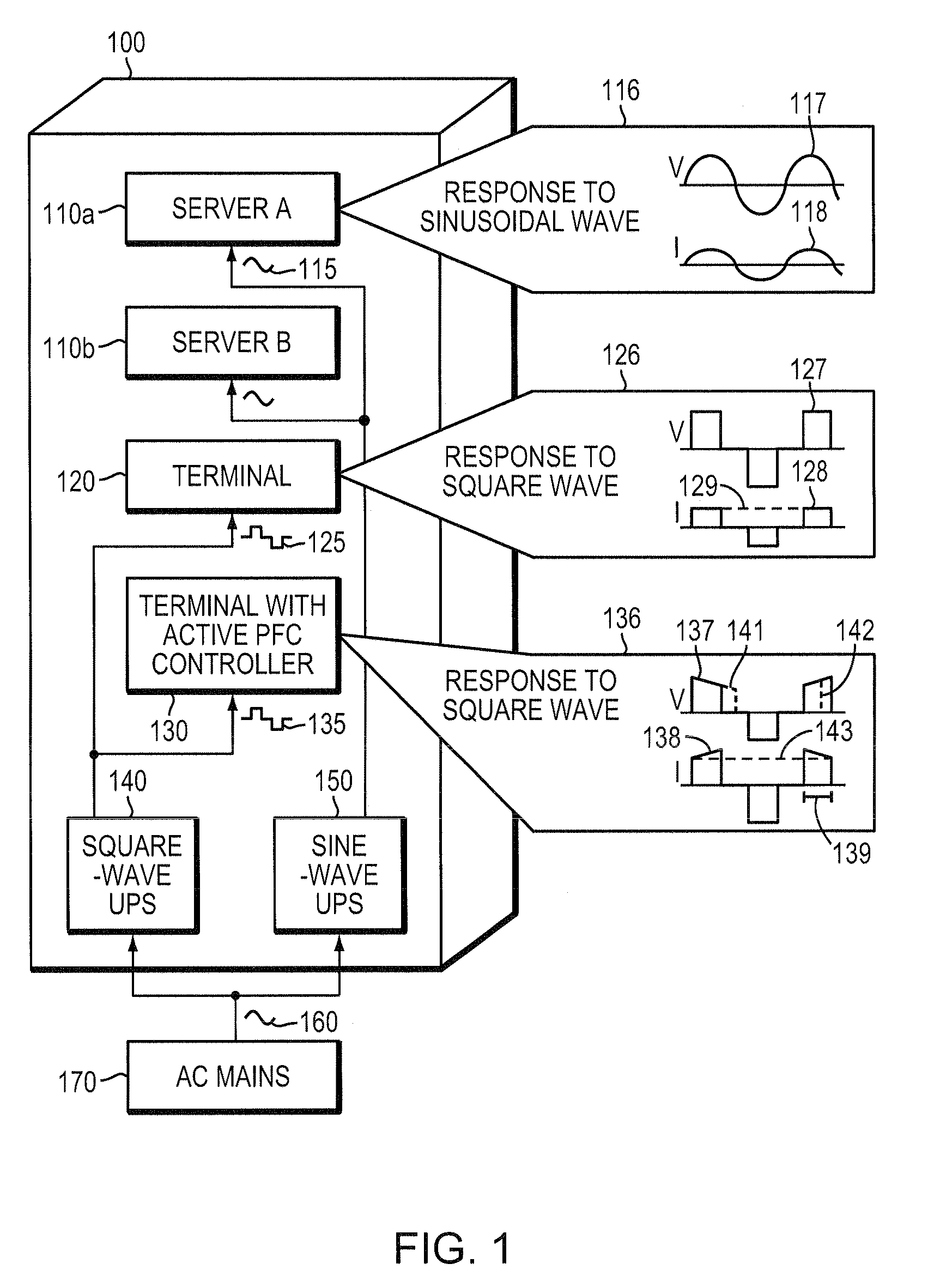
[0035]Uninterruptible Power Supply (UPS) systems with nonsinusoidal waveforms (in particular, square waveforms) have been found to be incompatible with a particular class of load characterized as an active power factor correction (PFC) load (i.e., having an active PFC controller). A general description of square waveforms and power factor correction, including active PFC, follows.

[0036]A square waveform (square wave) is a periodic waveform that typically includes, in one cycle, a “high” (constant) signal level for a given duration (duty width), followed by a region of zero signal level, and then a “low” signal level. Pulse width modulation is typically employed with square waves in UPS systems to modulate the duty width to achieve a desired output characteristic, such as a desired root mean square (RMS) voltage.

[0037]The power factor of a system, a dimensionless quantity between 0 and 1, is the ratio of the system's...


PUM


Abstract

Methods and apparatuses for providing a solution for incompatibility between nonsinusoidal waveform uninterruptible power supply (UPS) systems and active power factor correction (PFC) loads are disclosed. An embodiment of the invention includes generating a nonsinusoidal signal waveform (e.g., a voltage waveform), to be delivered to the load, with a pulse width modulation (PWM) duty width, sampling the nonsinusoidal signal waveform to collect output signal samples, and adjusting the duty width to control the nonsinusoidal signal waveform as a function of the output signal samples to deliver a desired signal characteristic (e.g., RMS signal level) to the load. In embodiments of the invention, the output duty width is adjusted differently in cases of rising and falling power consumption, respectively, by the load. Techniques disclosed herein find broad applicability in UPS systems and inverters and improve efficiency and reliability for end users and utility providers.

Description

RELATED APPLICATION(S)[0001]This application claims the benefit of U.S. Provisional Application No. 61 / 201,502, filed on Dec. 10, 2008. The entire teachings of the above application are incorporated herein by reference.BACKGROUND OF THE INVENTION[0002]Energy transmission via electric power systems is critical to modern civilization. Since numerous electric devices draw alternating current (AC) power from utility sources (i.e., line power from the electric power grid), power failures (i.e., outages or interruptions) can be a serious concern. The use of uninterruptible power supplies (UPSs) having battery back-up systems to provide regulated, uninterrupted power for sensitive and / or critical loads, such as computer systems, and other data processing systems is well known.[0003]Uninterruptible power supply (UPS) systems are commonly used in conjunction with a variety of electric devices to safeguard against power failures. UPS systems are available in various configurations to provide ...

Claims


Application Information

Patent Timeline
Patent Type & Authority Applications(United States)
IPC IPC(8): H02J9/00G05F1/10
CPCH02H3/40H02M7/53873H02M1/42
Inventor CHEN, HSIU-PINGFANG, SHENG-HSIENFENG, SHIH-HSIUNGSHEN, CHEN-JUI
Owner SCHNEIDER ELECTRIC IT CORP
Why Eureka
Try Eureka