
Display device, display control method, and electronic apparatus

a display device and control method technology, applied in the field of display devices, display control methods, electronic devices, to achieve the effect of reducing the influence of performance variation and highly accurate control of the amount of light supplied

Active Publication Date: 2010-06-10
JAPAN DISPLAY WEST
View PDF5 Cites 19 Cited by
  • Summary
  • Abstract
  • Description
  • Claims
  • Application Information

AI Technical Summary

Benefits of technology

[0011]In this present invention, the comparison between the output of the first detection element for detecting the light amount of outside light and the predetermined reference value and the comparison between the output of the second detection element for detecting dark current arising when light is blocked and the predetermined reference value are carried out by one comparator. This allows elimination of the influence of variation in the performance of the comparator.
[0013]Furthermore, by switching between the predetermined reference value used when the output of the first detection element is compared by the comparator and the predetermined reference value used when the output of the second detection element is compared by the comparator, an error of the calculation result due to variation in the performance between both the detection elements can be suppressed.
[0017]In this present invention, in the comparison between the output of the first detection element for detecting the light amount of outside light and the predetermined reference value and the comparison between the output of the second detection element for detecting dark current arising when light is blocked and the predetermined reference value by use of one comparator, switching between the comparison with the first detection element and the comparison with the second detection element is carried out. This allows elimination of the influence of variation in the performance of the comparator.
[0019]In this present invention, the comparison between the output of the first detection element for detecting the light amount of outside light and the predetermined reference value and the comparison between the output of the second detection element for detecting dark current arising when light is blocked and the predetermined reference value are carried out by one comparator. This allows elimination of the influence of variation in the performance of the comparator, and thus allows highly-accurate control of the amount of light supplied to the display area.

Problems solved by technology

However, applying a photosensor to a display device employing LTPS involves the following problems.

Method used


Image

  • Display device, display control method, and electronic apparatus
  • Display device, display control method, and electronic apparatus
  • Display device, display control method, and electronic apparatus

Examples


first embodiment

Configuration for Eliminating Influence of Individual Difference in Comparator Characteristics

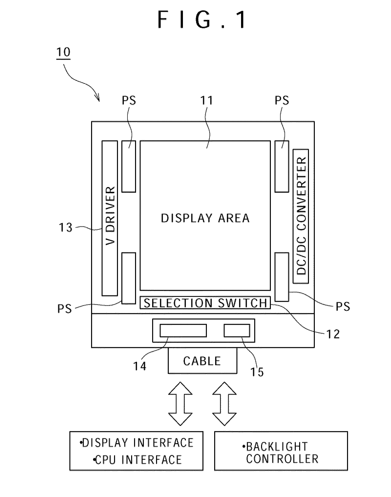
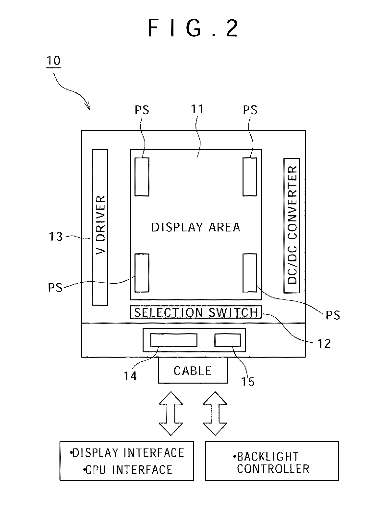
[0055]The present embodiment has the following circuit configuration. Specifically, based on a configuration that performs arithmetic operation for the outputs of the first photosensor that detects the light amount of outside light and the second photosensor that detects dark current arising when light is blocked as photosensors that are formed near the display area or in the display area on the same substrate, detection results are held by using the same comparator through switching between the first photosensor and the second photosensor, and the difference between these detection results is obtained by a difference calculation circuit.

[0056]In the conventional example shown in FIG. 23, dark current is automatically removed. However, removal of dark current on the output side is necessary when the method of FIG. 22 is used. In order to remove dark current, two photosensors are disposed an...

second embodiment

Configuration for Eliminating Influence of Individual Difference in Photosensor Characteristics

[0066]FIG. 4 is a circuit diagram for explaining major part of a display device according to a second embodiment. This display device is the same as the first embodiment (see FIG. 3) in that the display device includes the first photosensor PS1 that detects the light amount of outside light, the second photosensor PS2 that detects dark current arising when light is blocked, the changeover switches SW1 and SW2 for switching between the first photosensor PS1 and the second photosensor PS2, and the comparator 102. However, this display device is different from the first embodiment in that additional capacitance C connected to the output line common to the first photosensor PS1 and the second photosensor PS2 is variable and the reference value of the comparator 102 is variable.

[0067]The additional capacitance C in the display device of the present embodiment can be switched between when the fi...

third embodiment

Configuration for Avoiding Lowering of Resolution Dependent on Temperature and Outside Light Illuminance

[0086]The present embodiment is a scheme for avoiding the lowering of the resolution of the photosensor dependent on the temperature and the outside light illuminance with use of a display device having the configuration shown in FIGS. 4 and 5.

[0087]LTPS has a drastic temperature characteristic as the dark current (transistor leakage) characteristic as shown in FIG. 6. Therefore, in the case of a sensor circuit that charges the current flowing through the photosensor element in capacitance and outputs it as a time via the comparator in the configuration of the display device shown in FIGS. 4 and 5, the electric charges charged in the capacitance increase if dark current increases on the higher temperature side. This leads to a problem that the output time is shortened and thus the detection resolution is lowered.

[0088]To address this problem, in the present embodiment, the additio...


PUM


Abstract

A display device is provided and includes a first photosensor that detects the light amount of ambient light of a display area, a second photosensor that detects dark current arising when light is blocked, and changeover switches that select the first photosensor and the second photosensor. The display device further includes a comparator that compares the output of the selected first photosensor or second photosensor with a predetermined reference value, and control means that calculates the difference between the comparison result by the comparator with the first photosensor and the comparison result by the comparator with the second photosensor and controls the amount of light supplied to the display area corresponding to the calculation result. This configuration suppresses the influence of a detection error due to variation in the performance between the photosensors applied to the display device to thereby accurately adjust the amount of light supplied to the display area.

Description

TECHNICAL FIELD[0001]The present invention relates to a display device that displays predetermined video, a display control method for controlling the display device, and electronic apparatus employing a display device.BACKGROUND ART[0002]Conventionally, as a photosensor used for dimming control of a liquid crystal display device, the following ones are used. Specifically, in a liquid crystal display device employing an amorphous silicon TFT, as shown in FIG. 21, a constant current circuit is connected to the sensor output and photocurrent is detected through conversion of current into voltage.[0003]Furthermore, in the case of low-temperature poly-silicon (hereinafter, referred to as “LTPS”), a circuit can be formed on a substrate and thus a circuit configuration in which a comparator is connected to the sensor output as shown in FIGS. 22 and 23 is also possible. This circuit configuration allows a smaller circuit area and therefore the photosensor can be disposed in the periphery o...

Claims


Application Information

Patent Timeline
Patent Type & Authority Applications(United States)
IPC IPC(8): G09G5/10G06F3/038
CPCG01J1/32G01J1/46G02F1/13318G02F2001/133601G02F2001/133626G09G2360/144G09G2310/0237G09G2320/041G09G2320/0626G09G2320/0693G09G3/3406G09G2310/08G09G2360/145G02F1/133601G02F1/133626
Inventor NAKANISHI, TAKAYUKINAKAJIMA, YOSHIHARU
Owner JAPAN DISPLAY WEST
Learn More