Method and device for quantitatively determining the surface optical characteristics of a reference object comprised by a plurality of optically differentiable layers

a technology of optically differentiable layers and methods, applied in radiation pyrometry, instruments, material analysis, etc., can solve the problems of unsatisfactory adjustment, color measurement of these kinds of objects and the great specular reflectance of their surfaces, and lack of a physical model describing the optic behavior of dental restoration materials

Inactive Publication Date: 2010-06-10
APLIK
View PDF10 Cites 31 Cited by
  • Summary
  • Abstract
  • Description
  • Claims
  • Application Information

AI Technical Summary

Problems solved by technology

One of the main difficulties lies in the fact that, even within one single tooth, there is a wide range of hues (or chromaticity).
However, many of the hues of the natural teeth are not representative within this color spectrum in the guide, thus providing a reason why the adjustment found through this procedure is usually far from the aesthetic requirements desired by the patient.
These conditions affect the color selection, making the adjustment unsatisfactory in most cases.
An additional complication is the color measurement of these kinds of objects and the great specular reflectance their surfaces have.
The main inconvenience the Jung invention has derives from its lightning and capture system derived from fiber optics, which only permits taking spectrophotometric measurements of small portions of a tooth, so the capture procedure must be repeated to obtain measurements of a tooth total area.
In spite of the above, Berner lacks a physical model describing the optic behavior of a dental restoration materials and does not include in the selection procedure the fluorescence phenomenon characteristic of natural teeth.

Method used


Image

  • Method and device for quantitatively determining the surface optical characteristics of a reference object comprised by a plurality of optically differentiable layers
  • Method and device for quantitatively determining the surface optical characteristics of a reference object comprised by a plurality of optically differentiable layers
  • Method and device for quantitatively determining the surface optical characteristics of a reference object comprised by a plurality of optically differentiable layers

Examples


Embodiment Construction

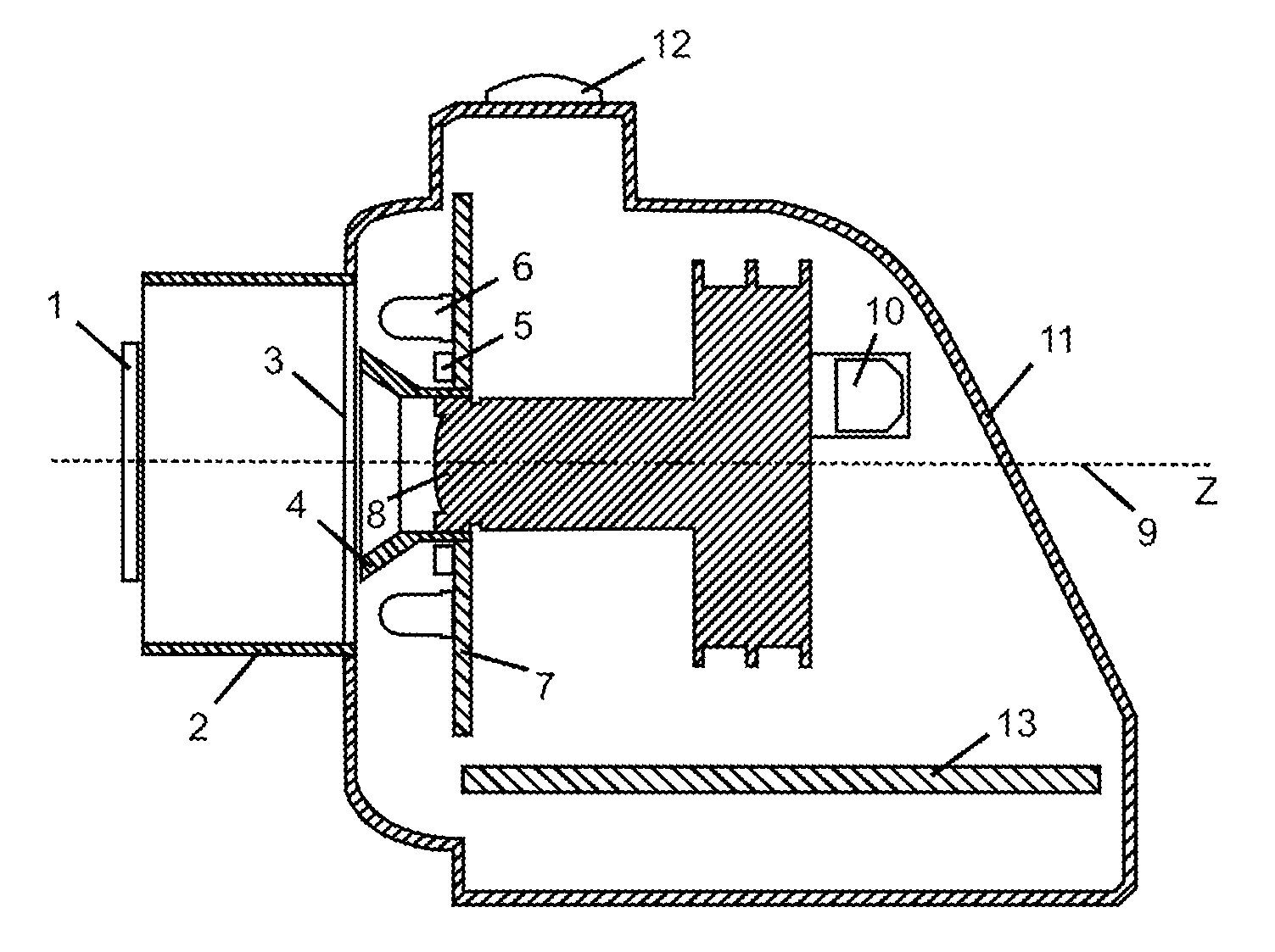
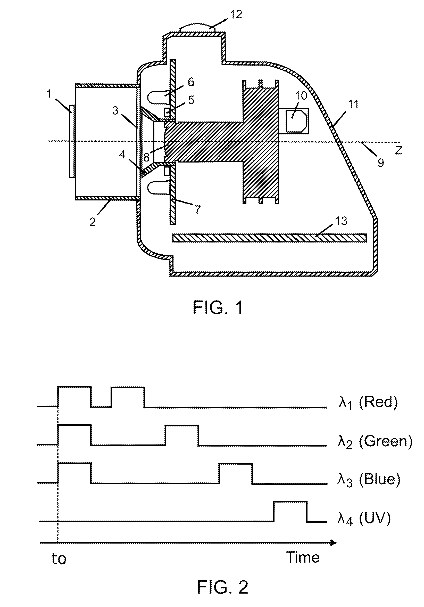
[0062]Many aspects of the invention can be better understood with the references made to the drawings below. The components in the drawings are not necessarily drawn to scale. Instead, emphasis is placed upon clearly illustrating the components of the present invention. Moreover, like reference numerals designate corresponding parts through the several views in the drawings.

[0063]FIG. 1 shows the schematic arrangement of the capture device (11) to obtain a dental image. The capture device (11) has annular lighting means (7), whose symmetry axis Z (9) corresponds to the normal joining the plane of the samples (1) to the lens in the digital image capture means (8). The position of the lighting means (7), in relation to the digital image capture means (8), has been conceived for the emitted light not to fall directly from its sources upon the optical elements of these digital image capture means (8).

[0064]The plane of the samples (1) is the place where the teeth of the patient or a sam...


PUM


Abstract

A method and device to determine quantitatively the surface optical characteristics of an object of reference made up of a plurality of optically differentiable layers. The device includes lighting and image capture means, connected to analysing means which execute the method to obtain the parameters of the repair material components best fitting the optical characteristics of the dental environment of the subject under treatment. The result of the analysis through the method in the invention consists mainly in the identification of each one of the various materials which should constitute the different layers, as well as their respective thicknesses, and which are to lead to a dental repair with optimum optical characteristics. It is thus achieved that the repair be visually imperceptible, both under natural light and under ultraviolet light.

Description

CROSS REFERENCE TO RELATED APPLICATIONS[0001]This application claims foreign priority benefit to Chilean Patent Application Number 3661-08 filed on Dec. 10, 2008, the entirety of which is hereby incorporated by reference.STATEMENT REGARDING FEDERALLY SPONSORED RESEARCH OR DEVELOPMENT[0002]This invention was not federally sponsored.FIELD OF THE INVENTION [0003]This invention is related to a method and a device to determine quantitatively the surface optical characteristics of an object of reference made up by a plurality of optically differentiable layers. Additionally and complementarily, a method is offered to determine a combination of layers of restoration or constitutive materials such as dental repair materials (usually synthetic resins, although they could be of an another nature), presenting surface optical characteristics similar to those of the object of reference.[0004]Referential application for the invention determines a combination of dental restoration materials, so th...

Claims


Application Information

Patent Timeline
Patent Type & Authority Applications(United States)
IPC IPC(8): G01J3/46G01B11/06
CPCG01B11/0625G01J3/02G01J3/0262G01J3/027G01J3/508G01J3/463G01J3/50G01J3/501G01J3/46
Inventor RAMIREZ MANCILLA, JAIMERUBIO AGUILAR, RODRIGOSERPELL CARRIQUIRY, DANIELSLUSARENKO FERNANDEZ, NICOLASVIDAL QUEVEDO, GUILLERMO
Owner APLIK
Why Eureka
Try Eureka