
Method for processing a digital signal in a digital delta-sigma modulator, and digital delta-sigma modulator therefor

a digital signal and digital delta technology, applied in the field of digital deltasigma modulators, can solve the problems of rapid incompatibility with high clock frequency, inability to carry propagation quantization, and inability to achieve high working frequency

Active Publication Date: 2010-06-10
STMICROELECTRONICS SRL +1
View PDF4 Cites 6 Cited by
  • Summary
  • Abstract
  • Description
  • Claims
  • Application Information

AI Technical Summary

Benefits of technology

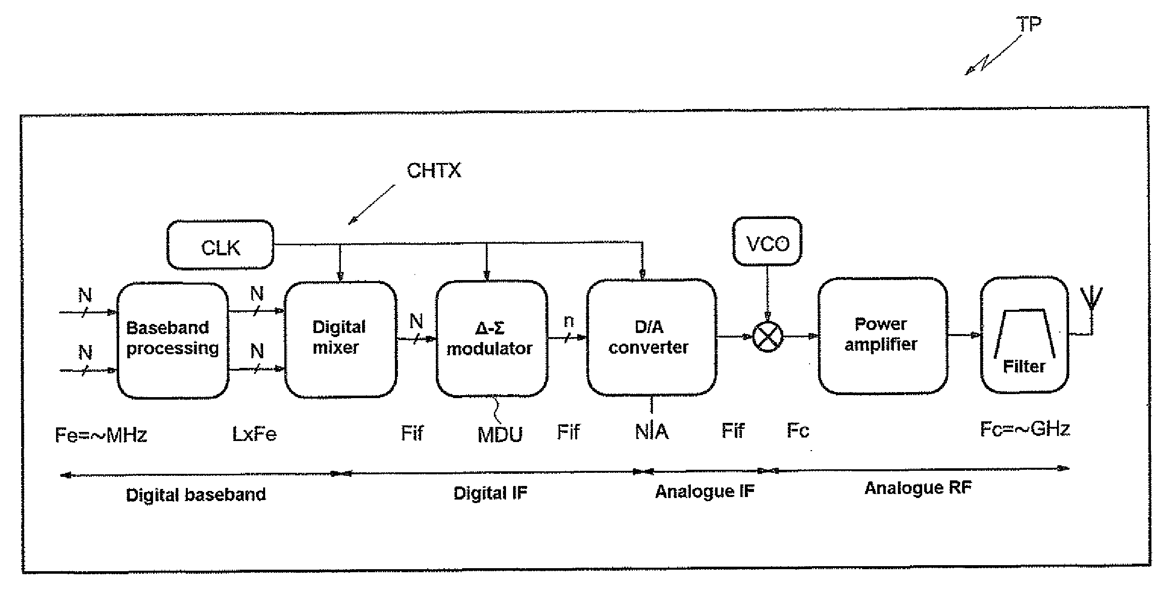
The present invention provides a method for processing a digital input signal using a digital delta-sigma modulator. The method involves formulating the output signal by anticipating the formulation of the filtered sampled signal and using a nonexact quantization. This allows for simultaneous delivery of the filtered sampled signal and the output signal to the modulator, and the quantized output signal to all the addition / subtraction modules of the modulator. The formulation of the output signal may be anticipated by formulating it in parallel with at least one of the elementary processes of formulating the filtered sampled signal. The method also allows for the use of a coding of the negative carry conservation type and the use of a chain of at least one adder / subtracter module. The invention also provides a digital delta-sigma modulator and an element of a wireless communication system incorporating the modulator. The technical effects of the invention include improved processing speed, reduced latency, and improved signal quality.

Problems solved by technology

This rapidly becomes incompatible with a high clock frequency.
However, the calculation of the quantization still requires a carry propagation.
This still proves to be incompatible with a high frequency clock signal.
However, whereas such an approach using a redundant arithmetic and a nonexact quantization of the output reduces the carry propagation time in the quantization calculation, this reduced calculation time admittedly makes it possible to operate at higher frequencies, but still proves to be incompatible for very high clock signal frequencies, such as those used in radio frequency applications, for example.

Method used


Image

  • Method for processing a digital signal in a digital delta-sigma modulator, and digital delta-sigma modulator therefor
  • Method for processing a digital signal in a digital delta-sigma modulator, and digital delta-sigma modulator therefor
  • Method for processing a digital signal in a digital delta-sigma modulator, and digital delta-sigma modulator therefor

Examples


Embodiment Construction

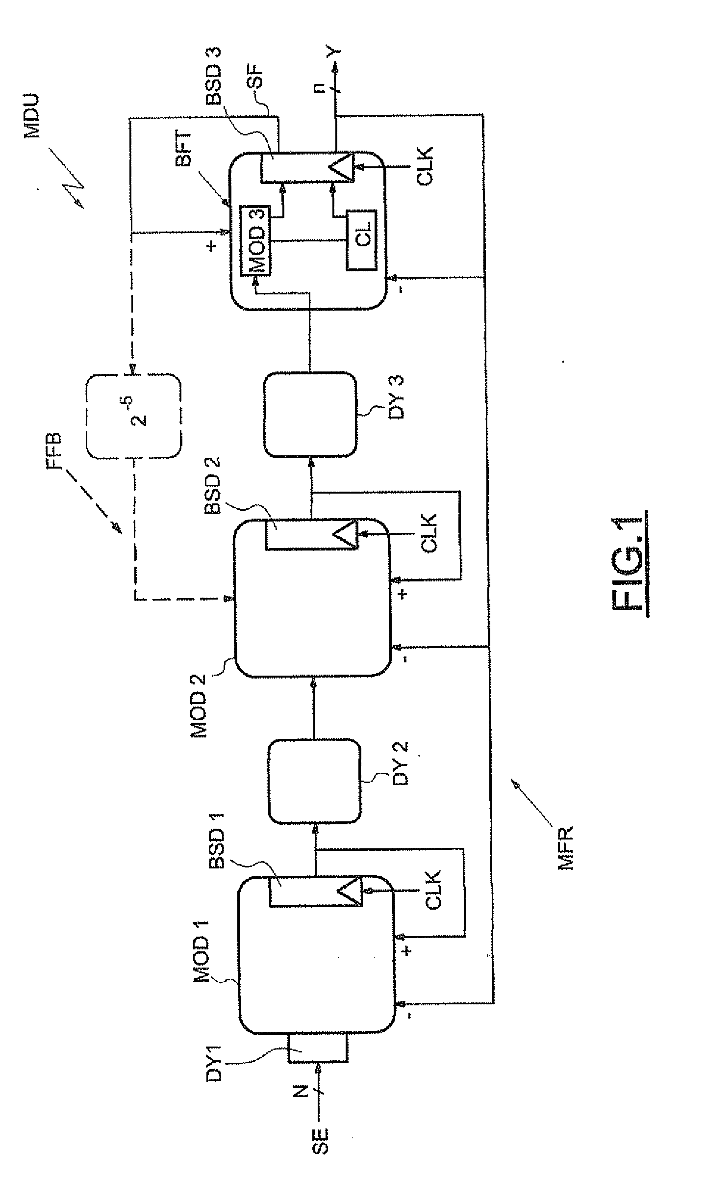
[0029]In FIG. 1, the reference MDU designates a delta-sigma modulator. This delta-sigma modulator essentially comprises looped filtering means or a looped filter MFR as well as quantization means or a quantizer CL.

[0030]Since the modulator MDU is of order 3, the filter MFR comprises three adder / subtracter modules MOD1, MOD2 and MOD3. The output of each of these modules is looped back to one of its inputs so as to perform an integration function. Moreover, the output data of each module are delivered by way of a flip-flop BSDi regulated by a clock signal CLK having a frequency Fs.

[0031]The modulator MDU receives as input a digital input signal SE sampled on N bits. Stated otherwise, the modulator MDU receives successive samples of N bits. The modulator MDU, and more particularly the quantizer CL, delivers by way of the flip-flop BSD3 of the final processing block BTF an output signal Y sampled on n bits, with n being less than N. In the nonlimiting example described here, n is equal ...


PUM


Abstract

The digital delta-sigma modulator includes a signal input for receiving digital samples of N bits, and a digital filter connected to the signal input. The digital filter performs addition / subtraction and integration operations according to a redundant arithmetic coding for delivering digital filtered samples. A quantizer performs a nonexact quantization operation so as to deliver digital output samples of n bits, with n being less than N. The input of the quantizer is connected within the digital filter.

Description

FIELD OF THE INVENTION[0001]The invention relates to digital delta-sigma modulators and applies advantageously, but not limitingly, to the transmission of radio frequency signals. More particularly, the invention applies wireless transmission devices such as cellular mobile telephones, for example, whose transmission chain incorporates a digital delta-sigma modulator.BACKGROUND OF THE INVENTION[0002]A digital delta-sigma modulator encodes a digital signal on a small number of levels, and at a sampling frequency that is much greater than the bandwidth of the signal to be encoded. The particular feature of such an encoder is its transfer function with respect to the quantization noise, which pushes the latter back out of the bandwidth of the signal. Thus, by a suitable filtering, the signal-to-noise ratio in the bandwidth is greatly improved with respect to conventional over-samplers.[0003]A conventional delta-sigma digital modulator comprises an input for receiving digital data sampl...

Claims


Application Information

Patent Timeline
Patent Type & Authority Applications(United States)
IPC IPC(8): H04L27/00G06F17/10H03M3/02
CPCH03M7/304H03M7/3026
Inventor CATHELIN, ANDREIAFRAPPE, ANTOINEKAISER, ANDREAS
Owner STMICROELECTRONICS SRL
Learn More