

Reception of signals transmitted over a dispersive optical channel
a dispersed optical channel and signal technology, applied in the field of optical communication, can solve the problems of limiting the amount of dispersion that can be compensated, limiting and ultimately limited the long-haul optical transmission system by distortion and degradation of transmitted signals. , to achieve the effect of improving the accuracy or reliability of information recovery and reducing the probability
- Summary
- Abstract
- Description
- Claims
- Application Information
AI Technical Summary
Benefits of technology
Problems solved by technology
Method used
Image

Examples
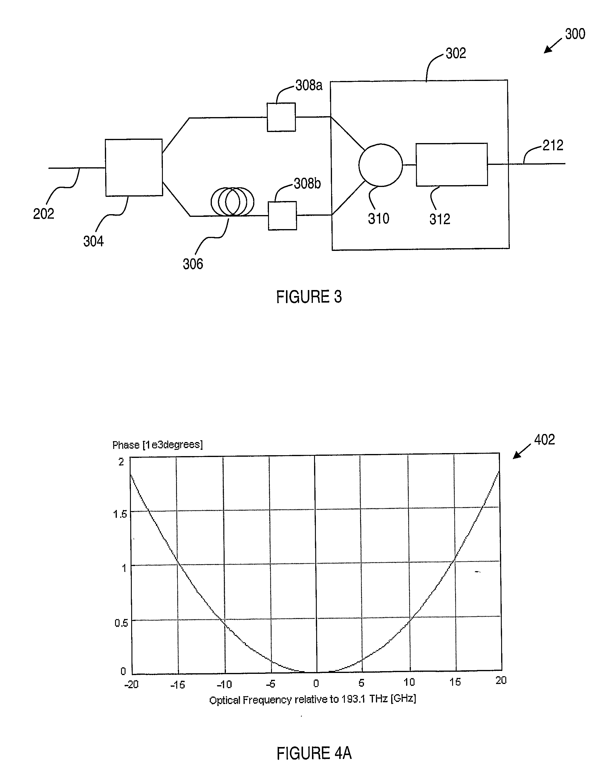
embodiment 300
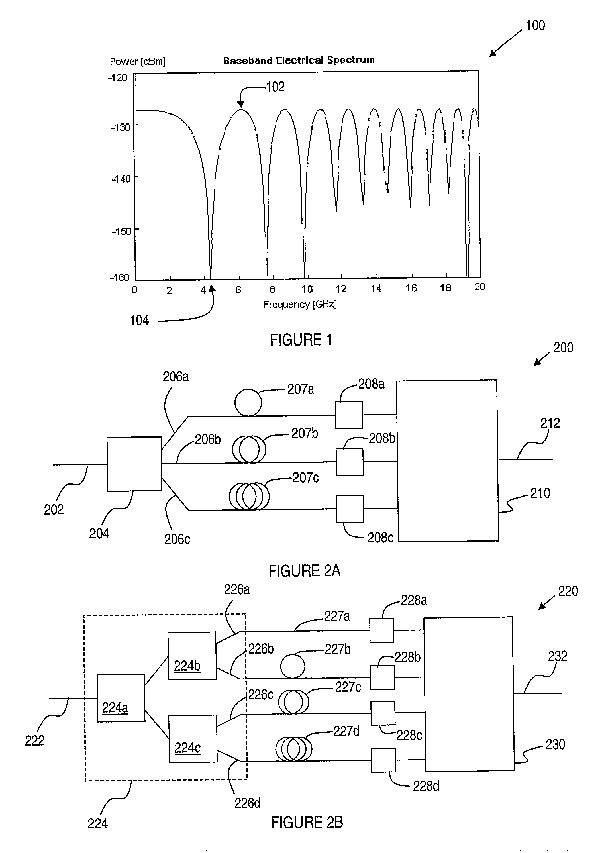
[0056]One approach to combining the detected signals within the signal processor 302 would therefore be to arrange the processor such that, for each signal bearing frequency component within the received electrical spectrum, the stronger, higher quality, detector output is selected. In some embodiments, this is indeed a practical approach, which is discussed in greater detail below with reference to FIGS. 6 to 8. However, in the embodiment 300, an alternative approach is applied. Specifically, the electronic signal processor 302 includes a signal combiner 310, for combining the respective electrical outputs of the detectors 308a, 308b. The signal combiner 310 may include analog electronic components, and may be, for example, a passive electrical power combiner. Alternatively, analog-to-digital converters and associated electronics may be operably connected to the electrical outputs of the detectors 308a, 308b, for the purpose of sampling and digitising the respective detected signal...
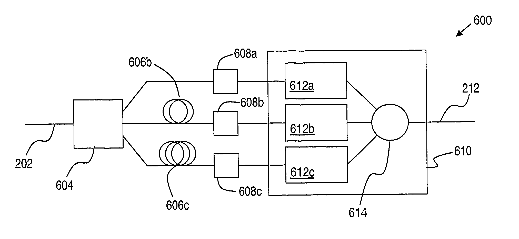
embodiment 600
[0063]Accordingly, in the embodiment 600 the signal processor 610 includes three distinct signal processing paths 612a, 612b, 612c each of which may generally include a combination of analog and digital electronic components.
[0064]FIG. 8 illustrates schematically a block diagram of an exemplary signal processing path 612, corresponding with a series of analog or digital components, and / or digital signal processing steps.
[0065]In particular, the exemplary signal processing path 612 includes an analog to digital converter 802, for sampling and digitising a detected signal. A serial-to-parallel converter 804 converts the sequence of digitised samples output from the analog-to-digital converter 802 into a corresponding parallel sequence. This is input to Fast Fourier Transform (FFT) block 806, the output of which, according to OFDM methods, is a set of parallel sampled signal values wherein each parallel output of the FFT 806 corresponds with one of the OFDM sub-carriers 702. Amplitude ...
embodiment 302
[0067]Furthermore, as noted above in relation to the discussion of FIG. 3, the exemplary signal processing path 612 may also be used in the embodiment 302, for processing of a single, pre-combined, electrical signal.
[0068]Turning now to FIG. 9A there is shown a graph 900 including channel responses 902, 904, 906 corresponding with three separate optical detectors, eg 608a, 608b, 608c at which the same received optical signal has experienced differing amounts of chromatic dispersion, by including additional dispersive elements, eg 606b, 606c, into at least two of the received signal paths. As a result, each channel response exhibits strong channel attenuation, or fading, in different groups of channels. The set of solid points 908 represents the best available signal quality for each OFDM sub-carrier channel, selected from the three available channel responses 902, 904, 906. As will be seen, it is possible by such selection for all OFDM channels to avoid the loss of signal quality, a...
PUM
 Abstract
Description
Claims
Application Information