Flexographic element and method of imaging

a technology of flexographic elements and printing plates, applied in the field of flexographic elements, can solve the problems of difficult to maintain small dots on flexographic printing plates, physical limitations of relief image creation process in flexographic printing plates, and difficult to print small graphic elements such as fine dots, lines, and even text using flexographic printing elements, etc., to achieve the effect of high throughput for individual imaging apparatus, no loss of small dots, and easy modification

Inactive Publication Date: 2010-06-10
EASTMAN KODAK CO
View PDF18 Cites 47 Cited by
  • Summary
  • Abstract
  • Description
  • Claims
  • Application Information

AI Technical Summary

Benefits of technology

[0041]Applicants have discovered a way to prepare a relief image without any loss in the strength of the small dots in that relief image. With the present invention, they can selectively control the relief image floor using a second frontside IR ablative exposure instead of a backside exposure using the same mask and exposing machine, leaving a perfectly registered relief image. In other words, a single mask layer can be used to define a relief image and floor pattern (that is multi-level pattern) by imaging from the same side using the same machine. This avoids the need to create a second mask for backside imaging. When backside exposure is used in combination with frontside exposure, a second exposing device is needed along with possibly two masks. The present invention eliminates the need for a ba

Problems solved by technology

While the quality of articles printed using flexographic elements has improved significantly in recent years, physical limitations related to the process of creating a relief image in the flexographic printing plate remain.
For example, it is very difficult to print small graphic elements such as fine dots, lines, and even text using flexographic printing elements.
Due t

Method used


Image

  • Flexographic element and method of imaging
  • Flexographic element and method of imaging
  • Flexographic element and method of imaging

Examples


embodiment 1

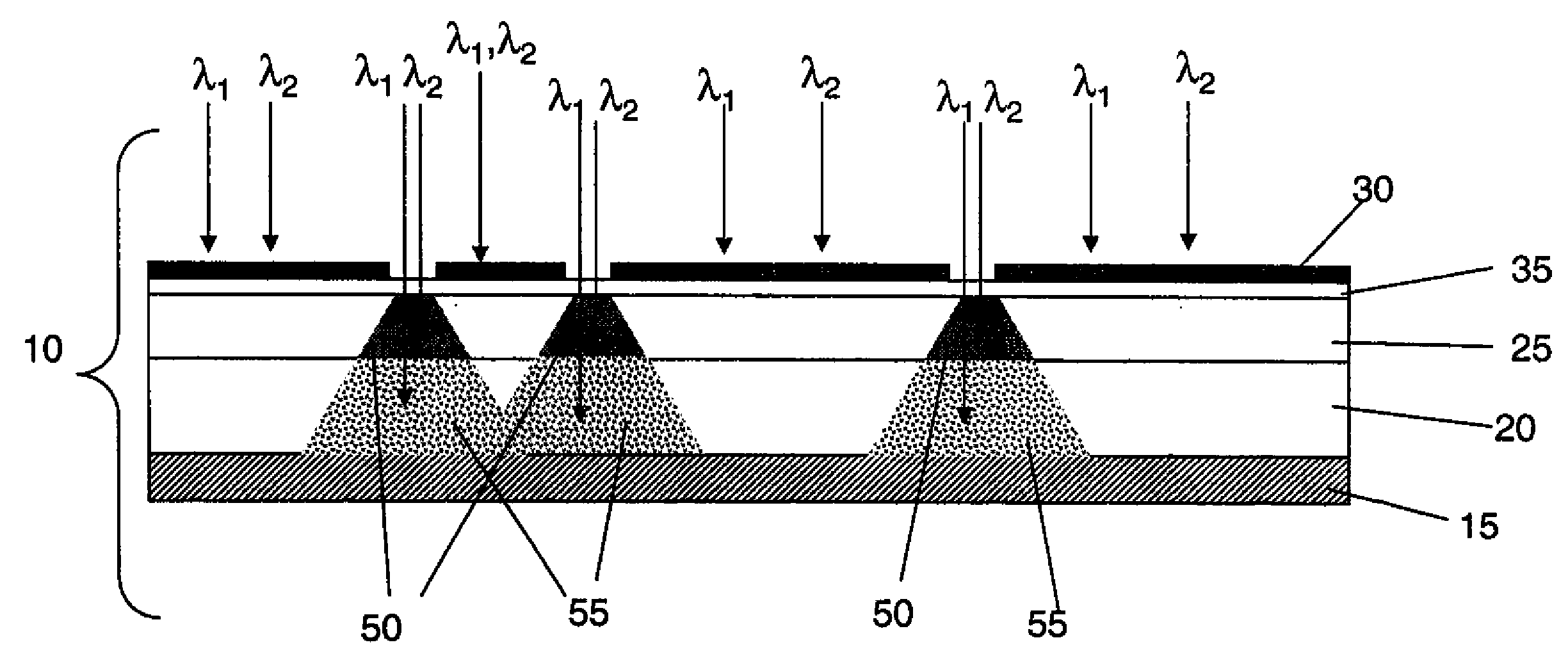
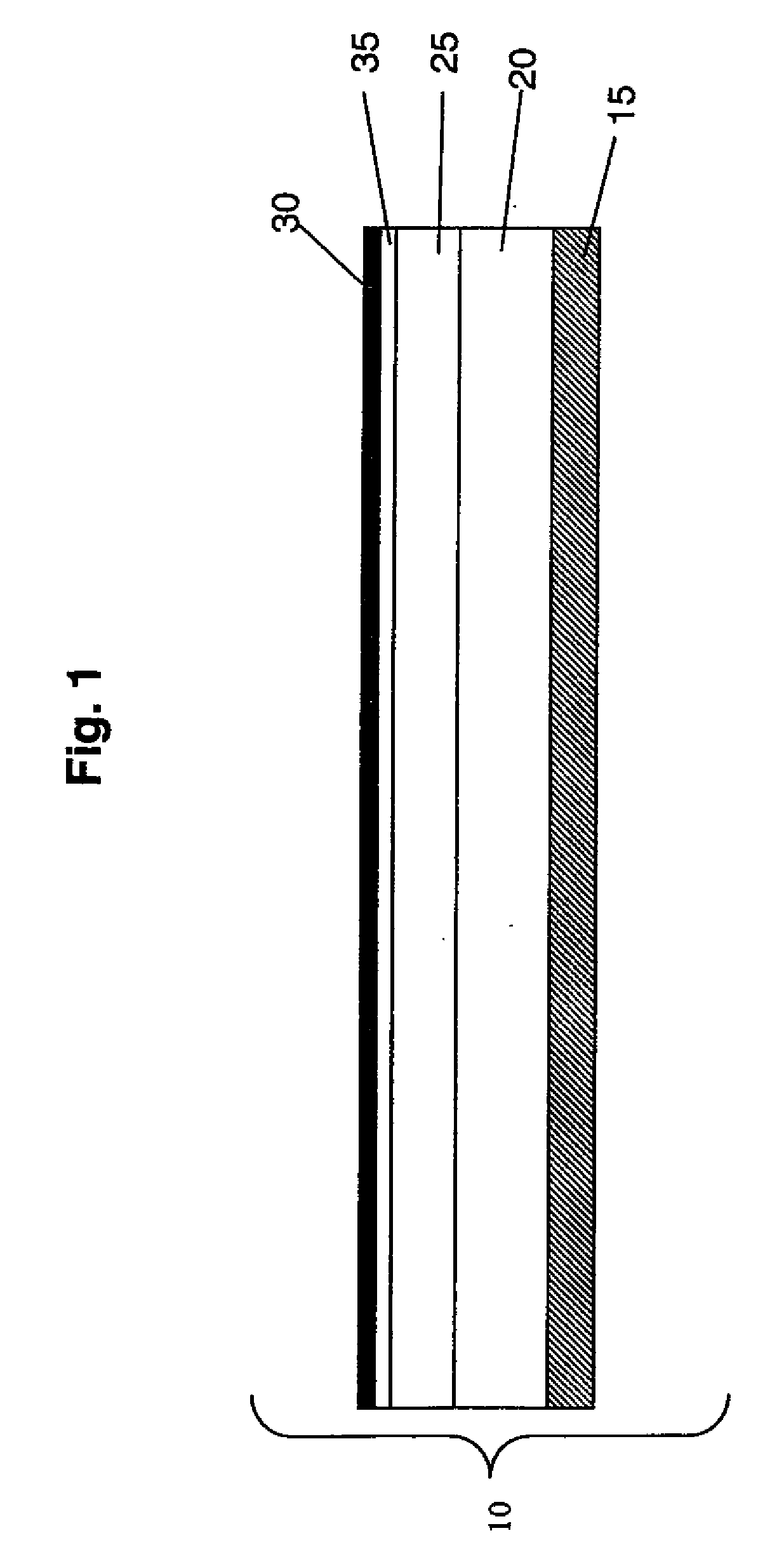
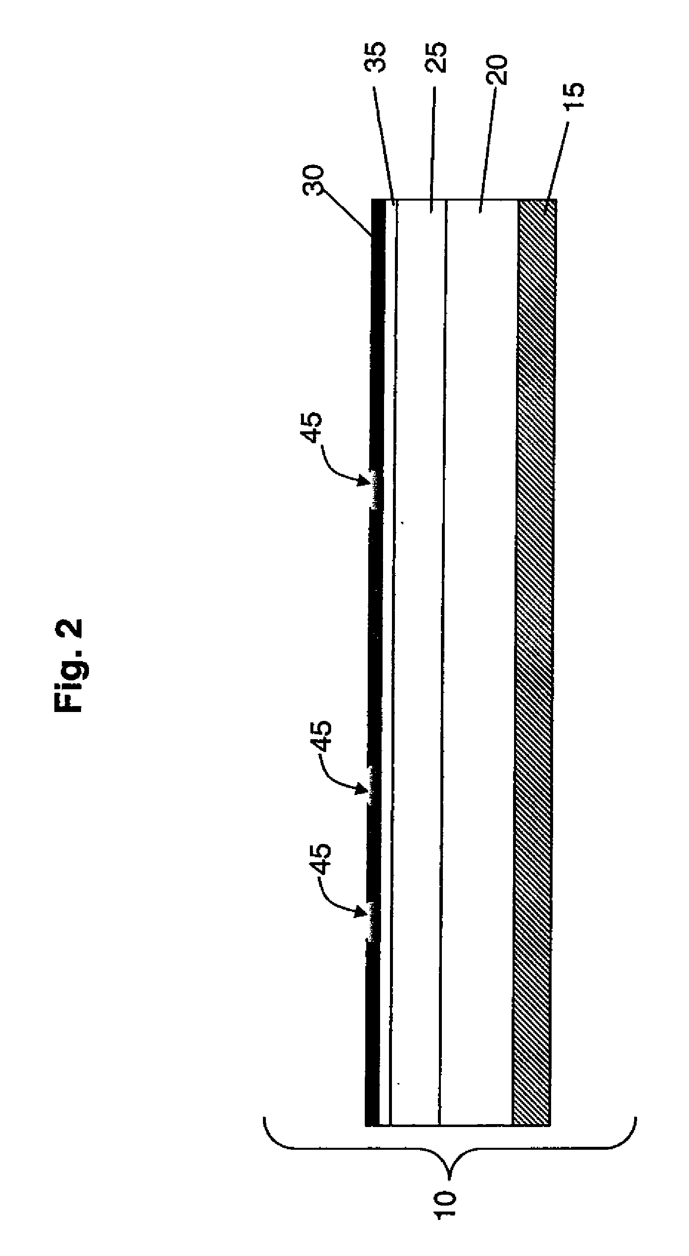
[0100]The first radiation-sensitive layer could contain Esacure KTO 46 photoinitiator at a concentration of 0.2 g / l making it sensitive to UV radiation between 360 to 400 nm. The second radiation-sensitive layer could contain Esacure KB1 at 0.01 g / l making it sensitive to UV radiation below 320 nm. The IR ablation layer could have the composition described in Table 1 of Example 1 of U.S. Pat. No. 7,279,254 (Zwadlo et al.) that is incorporated herein by reference.

embodiment 2

[0101]The first radiation-sensitive layer could contain Esacure KTO 46 photoinitiator at a concentration around 0.2 g / l making it sensitive to UV radiation between 360 to 400 nm. The second radiation-sensitive layer could contain Esacure KTO 46 at a concentration around 0.01 g / l making it sensitive to UV radiation below 340 nm. The IR ablation layer could have the composition described in Example 1 of U.S. Pat. No. 7,279,254 (noted above).

embodiment 3

[0102]The first radiation-sensitive layer could contain Esacure KTO 46 Photoinitiator at a concentration around 0.2 g / l making it sensitive to UV radiation between 360 to 400 nm. The second-radiation sensitive layer could contain Spectra Group H-Nu-IR-780 photoinitiator with peak sensitivity near 765 nm. The IR ablation layer could have the composition described in Table 1 of Example 1 of U.S. Pat. No. 7,279,254 (noted above).


PUM


Abstract

A relief (or flexographic) printing precursor has first and second radiation-sensitive layers, or a plurality of radiation-sensitive layers. The first radiation-sensitive layer is sensitive to a first imaging radiation having a first λmax. The second radiation-sensitive layer is disposed on the first radiation-sensitive layer and is sensitive to a second imaging radiation having a second λmax that differs from the first λmax by at least 25 nm. An infrared radiation ablatable layer can be present and is opaque or insensitive to the first and second imaging radiations and contains an infrared radiation absorbing compound. These relief printing precursors can be used to prepare flexographic printing plates, cylinders, or sleeves where the ablatable layer is used to form an integral mask on the element. Use of the invention provides a relief image without any loss in the strength of the small dots and can be carried out using multiple irradiation steps using the same apparatus.

Description

FIELD OF THE INVENTION[0001]This invention is directed to flexographic elements (or relief printing elements or precursors) that can be used in imaging methods to provide flexographic printing elements with relief images.BACKGROUND OF THE INVENTION[0002]Flexographic printing is a method of direct rotary printing that uses a resilient relief image in a plate of rubber or photopolymer to print articles such as cartons, bags, labels, or books. Flexographic printing has found particular application in packaging, where it has displaced photogravure and offset lithography printing techniques in many cases.[0003]Many methods of forming relief images are known in the graphic arts. Generally, photosensitive elements comprising an ablatable mask layer over a photosensitive polymer layer can be made into articles bearing relief images without the use of a photographic negative (graphic arts film) or other separate masking device. These photosensitive elements are formed into relief images by f...

Claims


Application Information

Patent Timeline
IPC IPC(8): G03F7/004G03F7/20
CPCG03F7/095G03F7/2022G03F7/202
Inventor VERES, JANOSSANGER, KURT M.
Owner EASTMAN KODAK CO
Why Eureka
Try Eureka