
Method of retrofitting a coal gasifier

a gasifier and coal technology, applied in the field of gasification systems, can solve the problems of difficult to ensure a steady supply of such large quantities of biomass, large system based on biomass as a feedstock, and large volume of oxygen and moistur

Active Publication Date: 2010-06-17
AIR PROD & CHEM INC
View PDF20 Cites 17 Cited by
  • Summary
  • Abstract
  • Description
  • Claims
  • Application Information

AI Technical Summary

Problems solved by technology

Sequestration of CO2, however, is a technology currently being developed and has not yet been demonstrated on an industrial scale.
However, biomass contains a large amount of oxygen and moisture as compared to coal.
It becomes difficult to ensure a steady supply of such large quantities of biomass.
Thus large systems based purely on biomass as a feedstock, tend to become practically unfeasible due to supply chain issues in procuring large quantities of feedstock.
Hence, dedicated biomass conversion facilities such as biomass-fired boilers or gasifiers are typically limited in sizes up to 25 MW thermal equivalent.
Such systems have been proposed and developed earlier, but these have faced numerous operational issues.
A few technology developers attempted to develop a system for biomass co-injection with coal, but such systems are typically limited to less than 5-10% of biomass by energy content.
Such co-injection approaches cannot be readily extended to larger amounts of biomass for example due to layer formation in the feeding and storage systems resulting from different densities, sizes, and shapes of coal and biomass particles.
These systems face multiple problems, not only with the gasifier, but also with auxiliary systems such as the feed handling systems.
For example, many types of biomass have a fibrous character that makes it difficult to grind as compared to relatively brittle coal.
A common size reduction setup cannot handle a mixture of coal and biomass, or cannot produce satisfactory results.

Method used


Image

  • Method of retrofitting a coal gasifier
  • Method of retrofitting a coal gasifier
  • Method of retrofitting a coal gasifier

Examples


examples

[0137]The following examples are presented to further illustrate certain embodiments of the present invention. These examples should not be read to limit the invention in any way.

[0138]Computational Fluid Dynamics (CFD) experiments, chemical equilibrium calculations and kinetic modeling of the gasifier were performed to illustrate some embodiments of the present invention.

[0139]A chemical equilibrium model of the co-gasification reactor is developed. Modeling of gasifier performance is conducted using Pittsburgh coal as a HCV feedstock and wood as a LCV HOC feedstock. Gasifier reactor is assumed to be adiabatic at a pressure of 30 atm. The chemical composition of the product stream was calculated assuming chemical equilibrium. The ultimate and proximate analyses of the fuels are shown in Table 1 presented in previous section. Table 2 lists the input streams to the gasifier, as well as calculated syngas product temperature, hydrogen and carbon monoxide mass flow rates, and H2 / CO rati...


PUM

PropertyMeasurementUnit
fuel flexibilityaaaaaaaaaa
particle sizeaaaaaaaaaa
energyaaaaaaaaaa

Abstract

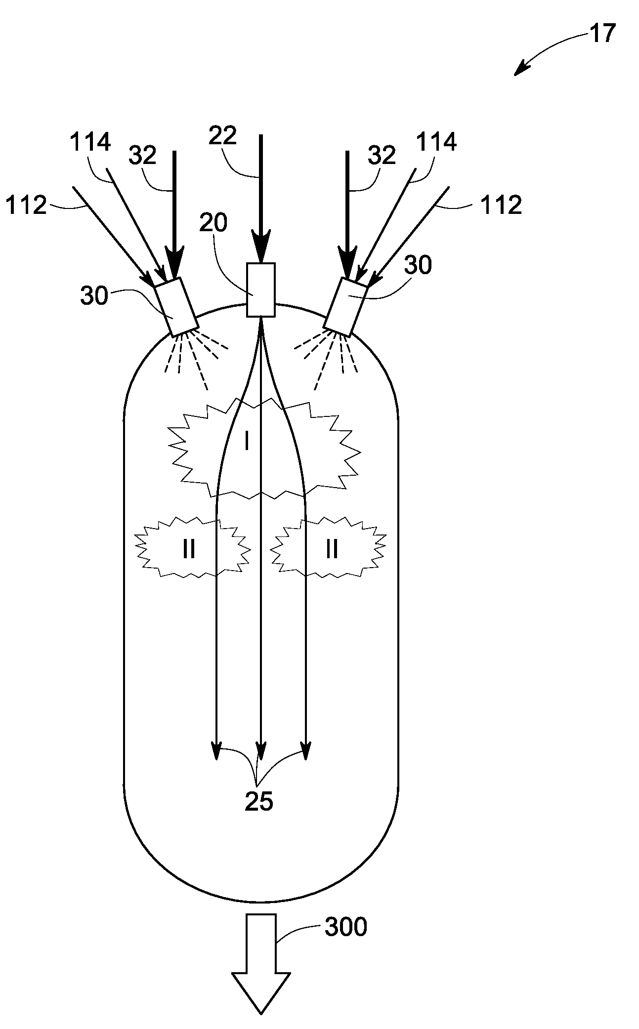
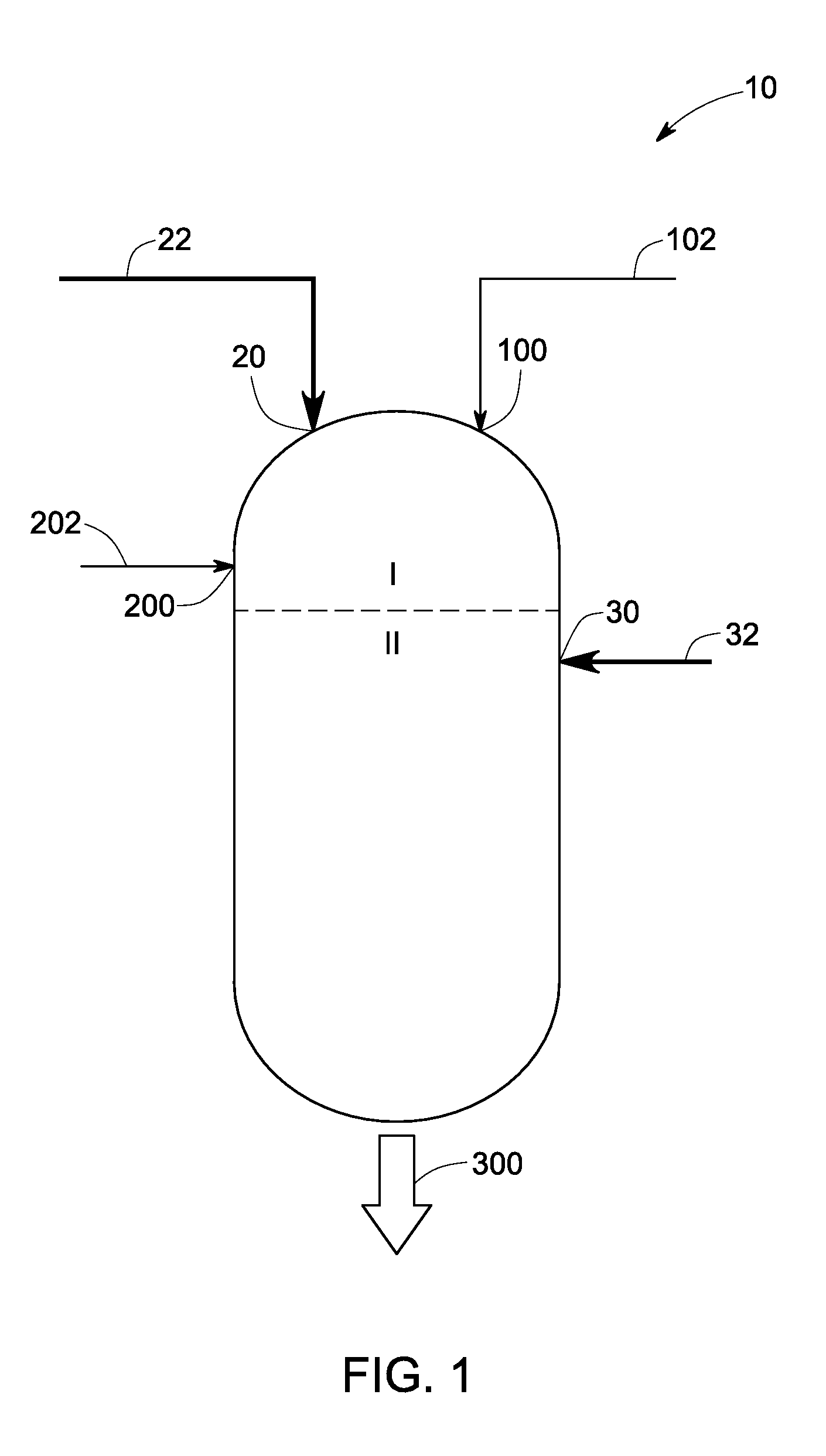
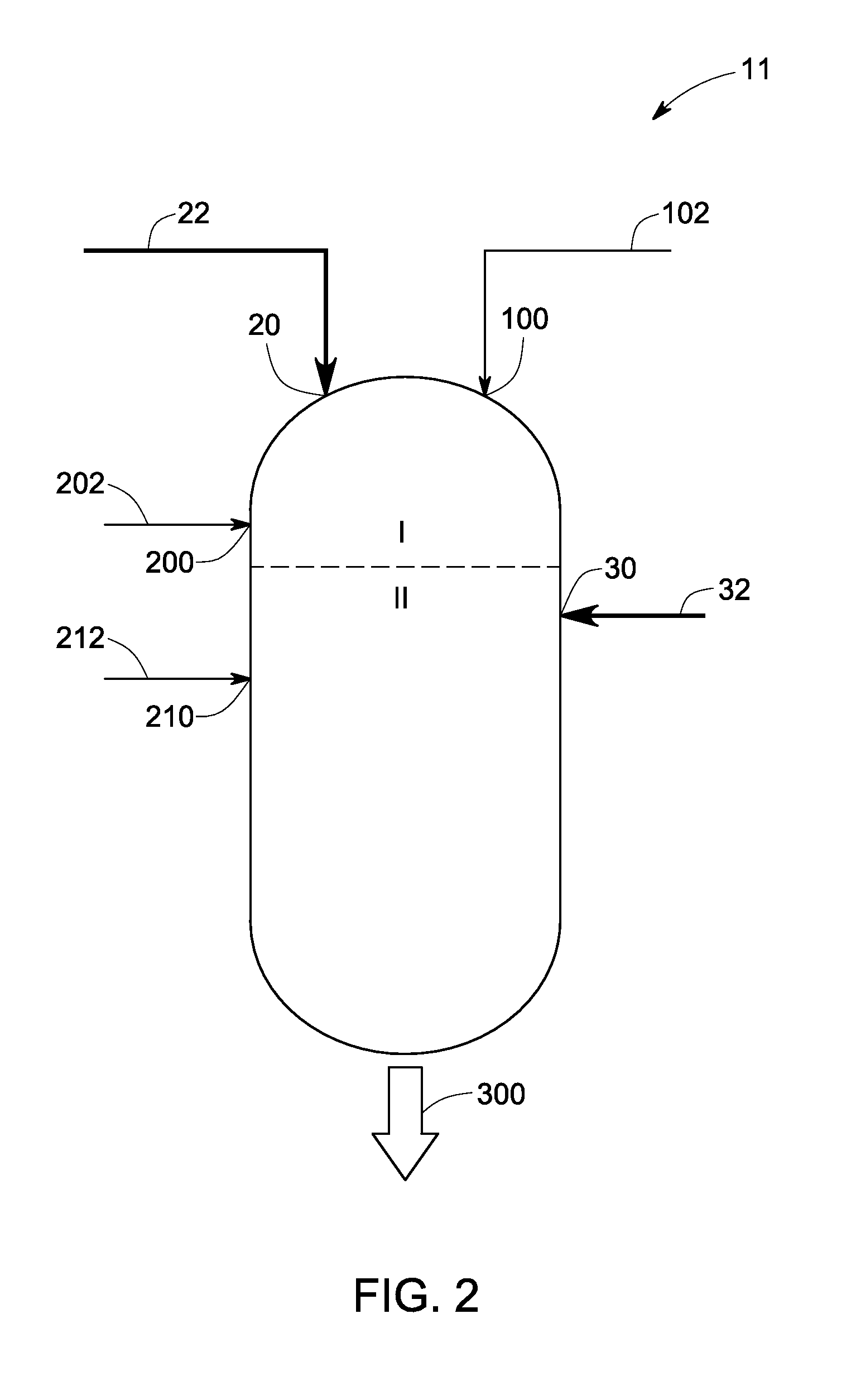
A coal gasifier is retrofitted to achieve multiple advantages such as reduced oxygen consumption, reduced CO2 and NOx emissions, better H:C ratio, better carbon conversion etc. This is achieved by dividing the coal into at least two zones and modifying the gasifier and operating it as described. The coal is injected into a first zone, configured to devolatilize a substantial portion of the injected coal to produce coal char and volatiles. The operation is tuned to substantially consume the oxidant injected in the first zone. A low-calorific-value, high oxidant feedstock is injected in second zone of the gasifier. The devolatilization of the low-calorific-value, high oxidant content feedstock provides the oxygen containing compounds which gasify at least a portion of the coal char generated in the first zone.

Description

CROSS REFERENCE TO RELATED APPLICATIONS[0001]This application is a continuation-in-part of U.S. Provisional Patent Application No. 61 / 121,560, titled ‘Multizone Co-Gasification,’ filed on Dec. 11, 2008, which is herein incorporated by reference.BACKGROUND[0002]The invention relates generally to a gasification system, and more particularly to a multifuel, multizone gasification system.[0003]Due to increasing crude prices, and relatively long term availability of coal, coal is being looked at as a one of the primary fuels of the future. Gasification of coal is an option that is environmentally more benign as compared to other methods of generating energy from coal, such as pulverized coal combustion. Coal gasification systems can be designed to remove CO2 before combustion of syngas produced as a result of gasification. Sequestration of CO2, however, is a technology currently being developed and has not yet been demonstrated on an industrial scale.[0004]Gasification of biomass is anot...

Claims


Application Information

Patent Timeline
Patent Type & Authority Applications(United States)
IPC IPC(8): C10J3/00C10J1/207
CPCY02E20/18C10J3/466C10J3/721C10J2300/1223C10J2300/0959C10J2300/0976C10J2300/0956Y02P20/145
Inventor ZAMANSKY, VLADIMIRLISSIANSKI, VITALIEITENEER, BORIS NIKOLAEVICHWEI, WEIJUPUDI, RAVICHANDRA SRINIVASASUBRAMANIAN, RAMANATHAN
Owner AIR PROD & CHEM INC
Learn More