Concurrent o2 generation and co2 control for advanced life support

a technology of co2 generation and advanced life support, which is applied in the direction of sulfur compounds, chemical separation, combinatorial devices, etc., can solve the problems of inability the weight of life support related technologies is currently too heavy for an astronaut to carry for a reasonable duration, and the deficit caused by weight of life support systems is also a deficit, so as to reduce the quantity of hea

Active Publication Date: 2010-06-17
UNIV OF FLORIDA RES FOUNDATION INC
View PDF8 Cites 25 Cited by
  • Summary
  • Abstract
  • Description
  • Claims
  • Application Information

AI Technical Summary

Benefits of technology

[0009]The device can also include at least one CO2 sensor in the outlet or at least one CO2 sensor in each of the chambers. The sensors provide a signal to a means to actuate the valves or other means to direct the gas flow. When a level of CO2 in the gas flow at the sensor exceeds a predetermined level of CO2, the first and second valves of all chambers positioned to be in the gas flow of the ventilation loop are positioned to restrict the gas flow to the chambers that have exceeded the predetermined CO2 level and place these chambers in communication with the second stage. The valves or other means of directing the gas flow of other chambers where the CO2 has been desorbed from the sorption beds are simultaneously or subsequently placed into the position such that

Problems solved by technology

Ostensibly, much of the technology needed for manned space travel is already in place but its weight is prohibitive.
Particularly, life support related technologies are currently too heavy for an astronaut to carry for a reasonable duration without exhaustion.
The deficit caused by weight for a life support system is also a deficit for other endeavors where a relatively long use of the system, including the use in a mining or other environment during emergency or other situations where the atmosphere is not conducive to breathing.
Current CO2 removal technol

Method used


Image

  • Concurrent o2 generation and co2 control for advanced life support
  • Concurrent o2 generation and co2 control for advanced life support
  • Concurrent o2 generation and co2 control for advanced life support

Examples


Embodiment Construction

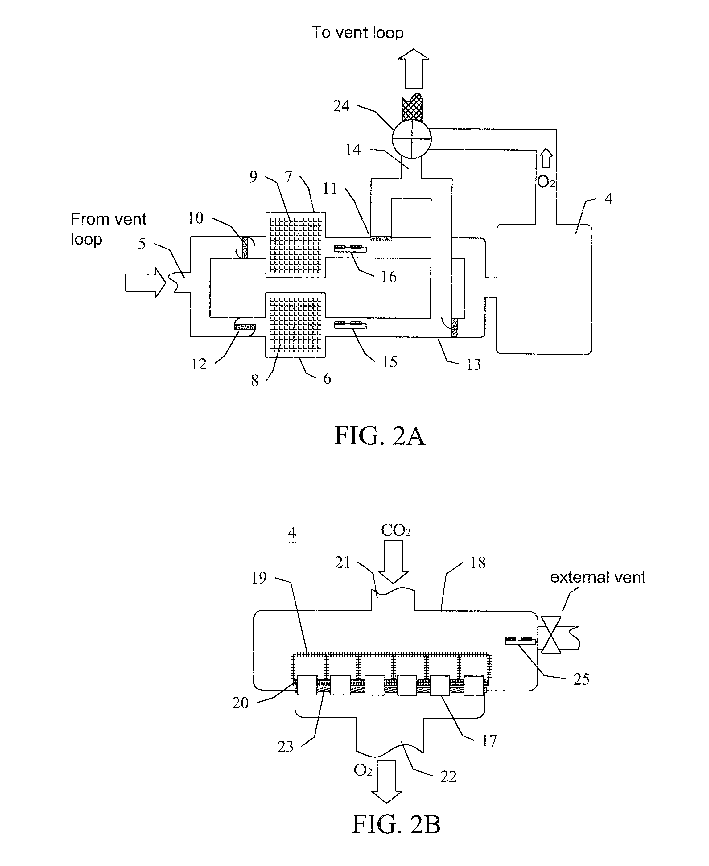
[0018]The present invention is a device for CO2 removal from and O2 addition to a life support system, such as a spacesuit. CO2 will be removed using a catalytic layer in series with a ceramic oxygen generator (COG) so that it is reduced to carbon and oxygen as in the chemical equation below:

CO2→C+O2

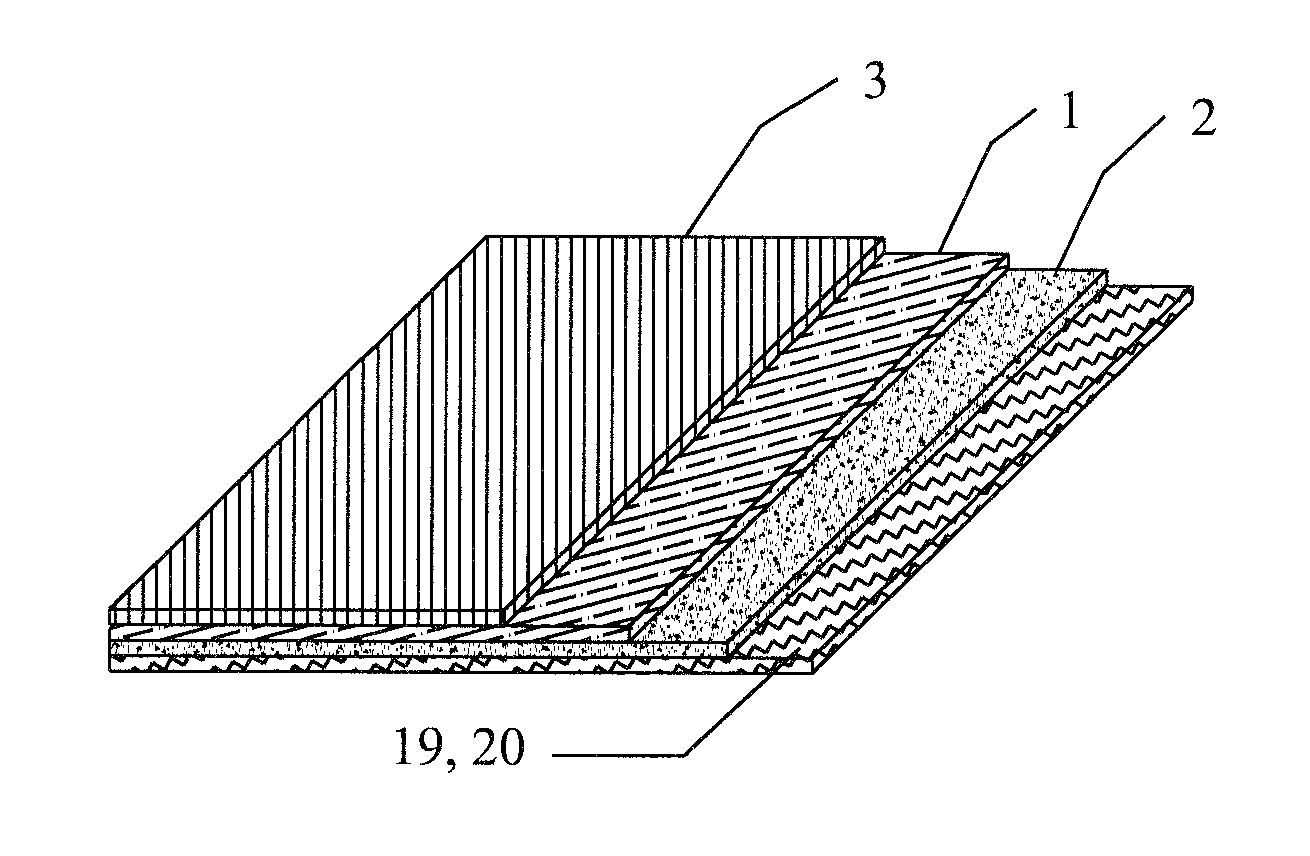
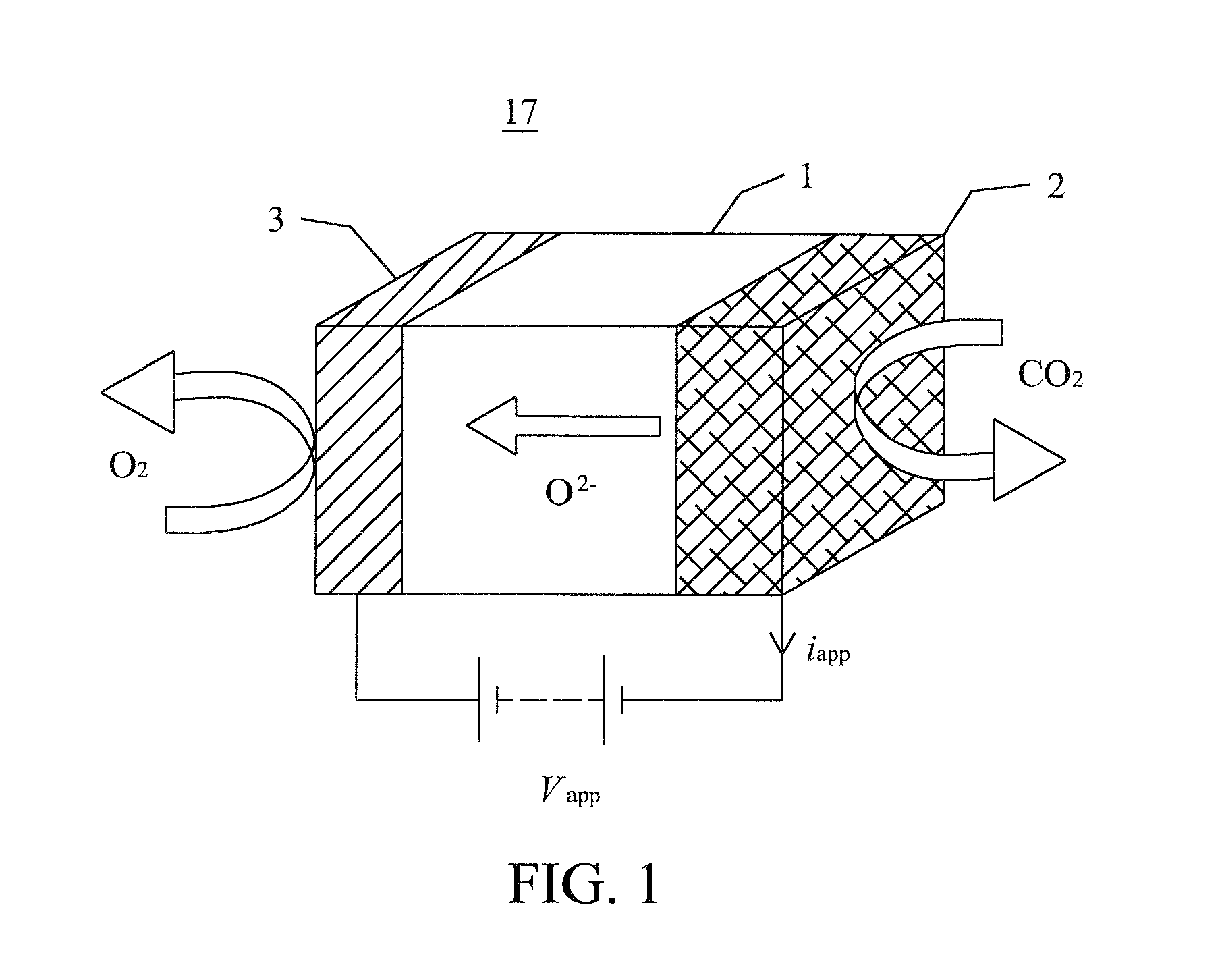
[0019]Carbon dioxide is electro-catalytically reduced at the cathode 2 of a COG 17, illustrated in FIG. 1, which transports the oxygen as O2− ions from the cathode 2 leaving behind solid carbon. The driving force is an electric potential applied across a dense oxide ion-conducting electrolyte 1, as shown in FIG. 1. Under the influence of this potential, CO2, adsorbed on the cathode 2, releases oxygen species, which are then incorporated into the lattice of the electrolyte 1 as oxide ions and transported to the anode 3, where they recombine to form O2 molecules. The oxygen flux is given by Faraday's equation:

JO2=iapp n−1F−1=Wapp Vapp−1n−1F−1

where JO2 is the molar flux of oxygen (mol / s),...


PUM

PropertyMeasurementUnit
Timeaaaaaaaaaa
Sizeaaaaaaaaaa
Flow rateaaaaaaaaaa

Abstract

A device for the concurrent oxygen generation and control of carbon dioxide for life support system involves two stages, where a first stage removes CO2 from an exhalent side of a ventilation loop and a second stage employs Ceramic Oxygen Generators (COGs) to convert CO2 into carbon and O2. The first stage includes a plurality of chambers and means to switch the ventilation loop through at least one of the chambers, where CO2 removal is carried out before discharge of the CO2 depleted gas to an inhalant side of the ventilation loop, and to exclude the ventilation loop from the remaining chambers of the first stage, where these chambers are placed in communication with the second stage. The second stage has two portions separated by the COGs such that CO2 and the formed carbon remain on an intake portion from the O2 rich atmosphere on the exhaust side, which is plumbed via a metering valve to introduce the O2 rich atmosphere to the inhalant side of the ventilation loop.

Description

CROSS-REFERENCE TO RELATED APPLICATION[0001]The present application claims the benefit of U.S. Provisional Application Ser. No. 60 / 926,909, filed Apr. 30, 2007, which is hereby incorporated by reference herein in its entirety, including any figures, tables, and drawings.GOVERNMENT SUPPORT[0002]The subject matter of this application has been supported by a research grant from the National Aeronautic and Space Administration under Grant No. NNJO6HB01C. Accordingly, the government has certain rights in this invention.FIELD OF THE INVENTION[0003]The invention relates to a device to generate oxygen concurrently with the reduction of CO2 for life support systems.BACKGROUND OF THE INVENTION[0004]Weight is one of the most crucial factors in determining the viability of manned space travel, such as a mission to mars. Ostensibly, much of the technology needed for manned space travel is already in place but its weight is prohibitive. Particularly, life support related technologies are currentl...

Claims


Application Information

Patent Timeline
IPC IPC(8): C01B13/02A62B7/08
CPCB01D53/04Y02C10/04B01D53/62B01D63/06B01D63/087B01D69/04B01D69/08B01D69/12B01D71/024B01D2256/12B01D2257/504B01D2259/40088B01D2325/10B64G1/48B64G6/00C01B13/0203C25B1/02B01D53/32Y02C20/40Y02P20/151
Inventor WACHSMAN, ERIC D.DUNCAN, KEITH L.HAGELIN-WEAVER, HELENA
Owner UNIV OF FLORIDA RES FOUNDATION INC
Why Eureka
Try Eureka