Plastification and injection unit with back-flow barrier

a backflow barrier and injection unit technology, applied in the field of plastification and injection units, can solve the problems of unavoidable disassembly of cleaning in the case of conventional constructions, relative complexity of structure, and inability to clean injection units, etc., to achieve fast external activation, reduce cleaning effort, and simple structure

Active Publication Date: 2010-06-17
KLOECKNER DESMA ELASTOMERTECHN
View PDF4 Cites 0 Cited by
  • Summary
  • Abstract
  • Description
  • Claims
  • Application Information

AI Technical Summary

Benefits of technology

[0012]The main advantage is the simple structure in the region of the injection mass. The entire construction essentially consists of two individual parts. Threaded connections and fittings that are susceptible to failure, in the region of the high mass pressure (injection piston / injection cylinder) are no longer required. The injection piston, i.e. the back-flow barrier, no longer has to be disassembled for thorough cleaning, thereby significantly reducing the cleaning effort and precluding damage that results from incorrect handling. Furthermore, because of the targeted, powerful, and therefore fast external activation, a reduction in the leakage flow is achieved. The volume injected into the mold can thus be metered in a significantly more precise manner. In order to allow lower scrap rates and in order to be able to implement fully automated systems, low variations in the injection volume between the individual injection procedures are very important.

Problems solved by technology

As stated, the movable part is situated in a separate chamber in the injection piston, thereby resulting in a relatively complicated structure.
The injection channel from the screw cylinder to the piston outlet and the chamber for the movable part can, of course, become clogged during operation, by material that hardens, so that the injection unit frequently has to be cleaned.
If this is to happen in a reasonable manner, disassembly for cleaning is unavoidable in the case of the conventional constructions.
The slightest assembly errors (e.g. overlooked dirt particles or deficient lubrication) very quickly lead to failure of the entire construction.
The regular cleaning of the injection unit that is actually required is therefore very time-consuming and risky at present.
A possible production failure is a threat.
The old deposits that result from this, which burst off out of the injection unit and enter the molded parts, cause high scrap rates.

Method used


Image

  • Plastification and injection unit with back-flow barrier
  • Plastification and injection unit with back-flow barrier
  • Plastification and injection unit with back-flow barrier

Examples


Embodiment Construction

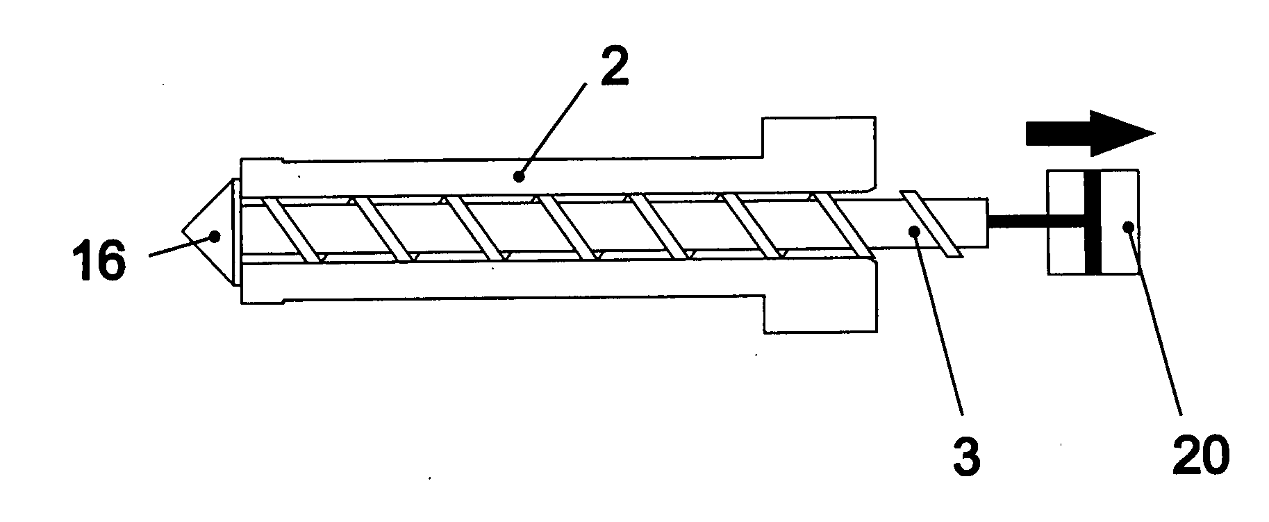
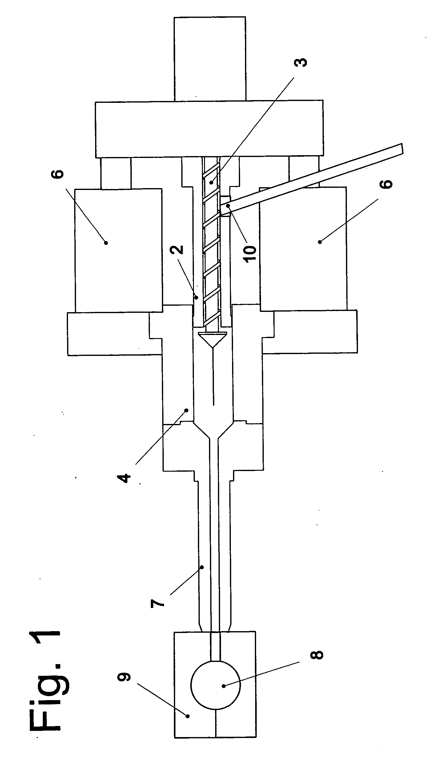
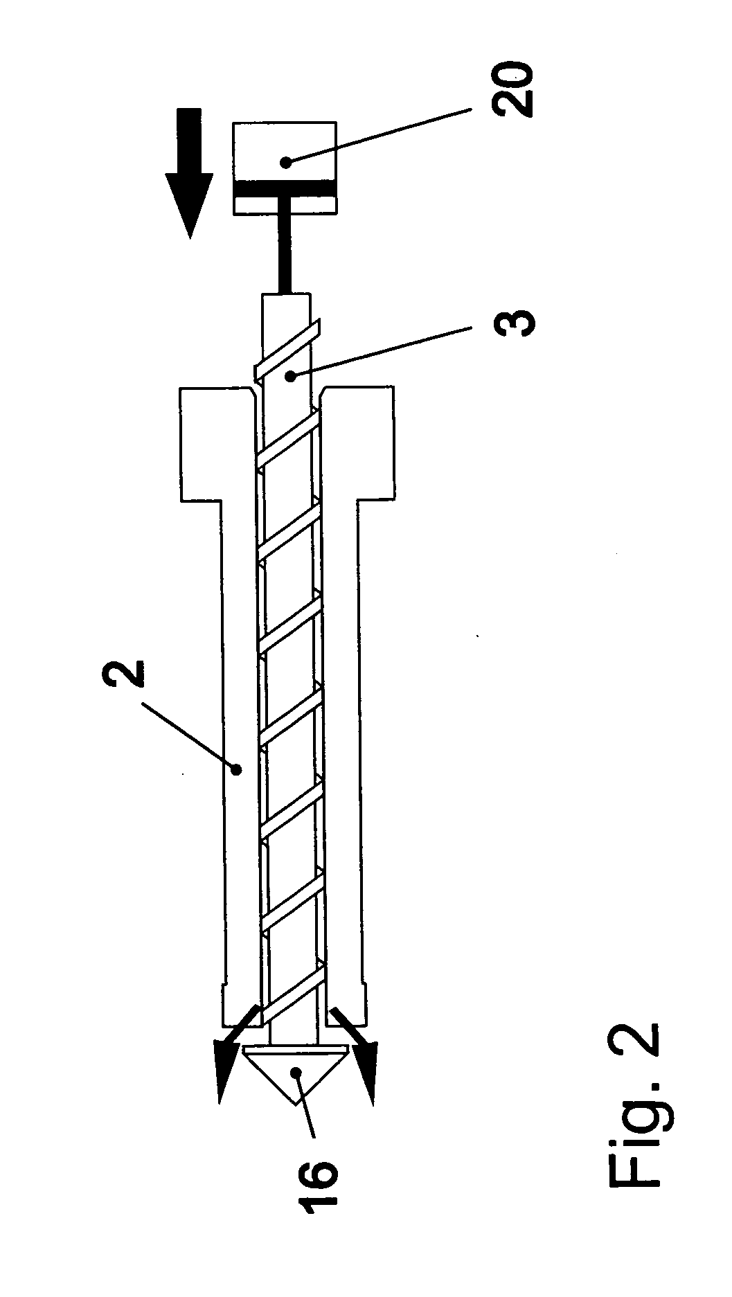
[0021]FIG. 1 shows a plastification and injection unit generally indicated with the reference symbol 1. Unit 1 consists essentially of a plastification screw 3 disposed in a screw cylinder 2 so as to rotate. Screw cylinder 2 serves as an injection piston for the mass plasticized by screw 3, which is pressed into the injection cylinder using the so-called FIFO method (first in-first out). When injection cylinder 4 is filled, screw cylinder 2 is moved into injection cylinder 4 by means of hydraulic cylinders 6, thereby pressing the plasticized mass out of the injection cylinder into cavity 8 of an injection-molding die 9, by way of nozzle 7.

[0022]The number 10 refers to the intake shaft in the screw cylinder for the material (rubber) to be plasticized.

[0023]In the prior art according to FIGS. 4 to 6, the screw cylinder is structured in multiple parts. It consists of the actual cylinder for accommodating the screw and a region referred to as the back-flow barrier 11. Back-flow barrier ...


PUM

PropertyMeasurementUnit
axial displacementaaaaaaaaaa
pressureaaaaaaaaaa
mass pressureaaaaaaaaaa

Abstract

A plastification and injection unit in injection-molding machines for processing of polymer materials, for example rubber, has a plastification screw that is disposed so as to rotate in a screw cylinder, which simultaneously represents the injection piston. The screw cylinder is disposed in an injection cylinder, in an axially displaceable manner. The injection cylinder can be connected with the sprue channel of an injection-molding die by way of a nozzle, and the injection piston has a back-flow barrier. The screw is axially displaceable in the screw cylinder by means of a separate drive. The screw tip projects out of the screw cylinder and has a closure body having a sealing surface for contact with the face surface of the screw cylinder.

Description

CROSS REFERENCE TO RELATED APPLICATIONS[0001]Applicants claim priority under 35 U.S.C. §119 of German Application No. 10 2008 061 845.4 filed Dec. 15, 2008 and German Application No. 10 2009 008 590.4 filed Feb. 12, 2009.BACKGROUND OF THE INVENTION[0002]1. Field of the Invention[0003]The invention relates to a plastification and injection unit in injection-molding machines, for processing of polymer materials, for example rubber. The unit has a plastification screw that is disposed so as to rotate in a screw cylinder. The screw cylinder simultaneously represents the injection piston, which is disposed in an injection cylinder, in an axially displaceable manner. The injection cylinder can be connected with the sprue channel of an injection-molding die by way of a nozzle, and the injection piston has a back-flow barrier.[0004]2. The Prior Art[0005]These types of injection units work according to the so-called FIFO principle (first in-first out). During the plastification phase (fillin...

Claims


Application Information

Patent Timeline
Patent Type & Authority Applications(United States)
IPC IPC(8): B29C45/23
CPCB29C45/532B29C45/52
Inventor KUECHLER, OLAFBAUMANN, EDWINKRELL, VOLKER
Owner KLOECKNER DESMA ELASTOMERTECHN
Why Eureka
Try Eureka