Eureka AIR delivers breakthrough ideas for toughest innovation challenges, trusted by R&D personnel around the world.

Cathode filter replacement algorithm in a fuel cell system

Inactive Publication Date: 2010-06-17
GM GLOBAL TECH OPERATIONS LLC
View PDF3 Cites 21 Cited by
  • Summary
  • Abstract
  • Description
  • Claims
  • Application Information

AI Technical Summary

Benefits of technology

[0010]In accordance with the teachings of the present invention, a fuel cell system is disclosed that includes a compressor for providing cathode air to the cathode side of a fuel cell stack and an air filter for filtering the air sent to the compressor to prevent particulates and other contaminants from entering the compressor and the fuel cell stack. The fuel cell system also includes a mass flow meter that measures the flow of air to the compressor and a pressure sensor that measures the pressure of the airflow at the output of the compressor.

Problems solved by technology

MEAs are relatively expensive to manufacture and require certain conditions for effective operation.
Air filters for fuel cell systems are typically more complex than a typical internal combustion engine air filter, often filtering to HEPA standards of 0.3μ as opposed to 10-15μ for an internal combustion engine air filter.
If the air filter is restricted, the inlet to the compressor becomes depressed, which limits the fuel cell system's maximum power while consuming additional energy, further reducing performance.
Further, for a turbo-compressor, if the air filter fails as a result of being torn or otherwise mispositioned as a result of the force of the compressor air pulling on the air filter, dust and other contaminants that may enter the compressor may damage the compressor and its air bearings.
Currently, without a dedicated compressor inlet pressure sensor, no technique or process is used in the art for detecting when the air filter in the fuel cell system should be replaced, which otherwise might cause compressor failure.

Method used


Image

  • Cathode filter replacement algorithm in a fuel cell system
  • Cathode filter replacement algorithm in a fuel cell system
  • Cathode filter replacement algorithm in a fuel cell system

Examples


Embodiment Construction

[0014]The following discussion of the embodiments of the invention directed to a fuel cell system employing an algorithm for determining when a compressor air filter needs to be changed using a compressor map is merely exemplary in nature, and is in no way intended to limit the invention or its applications or uses.

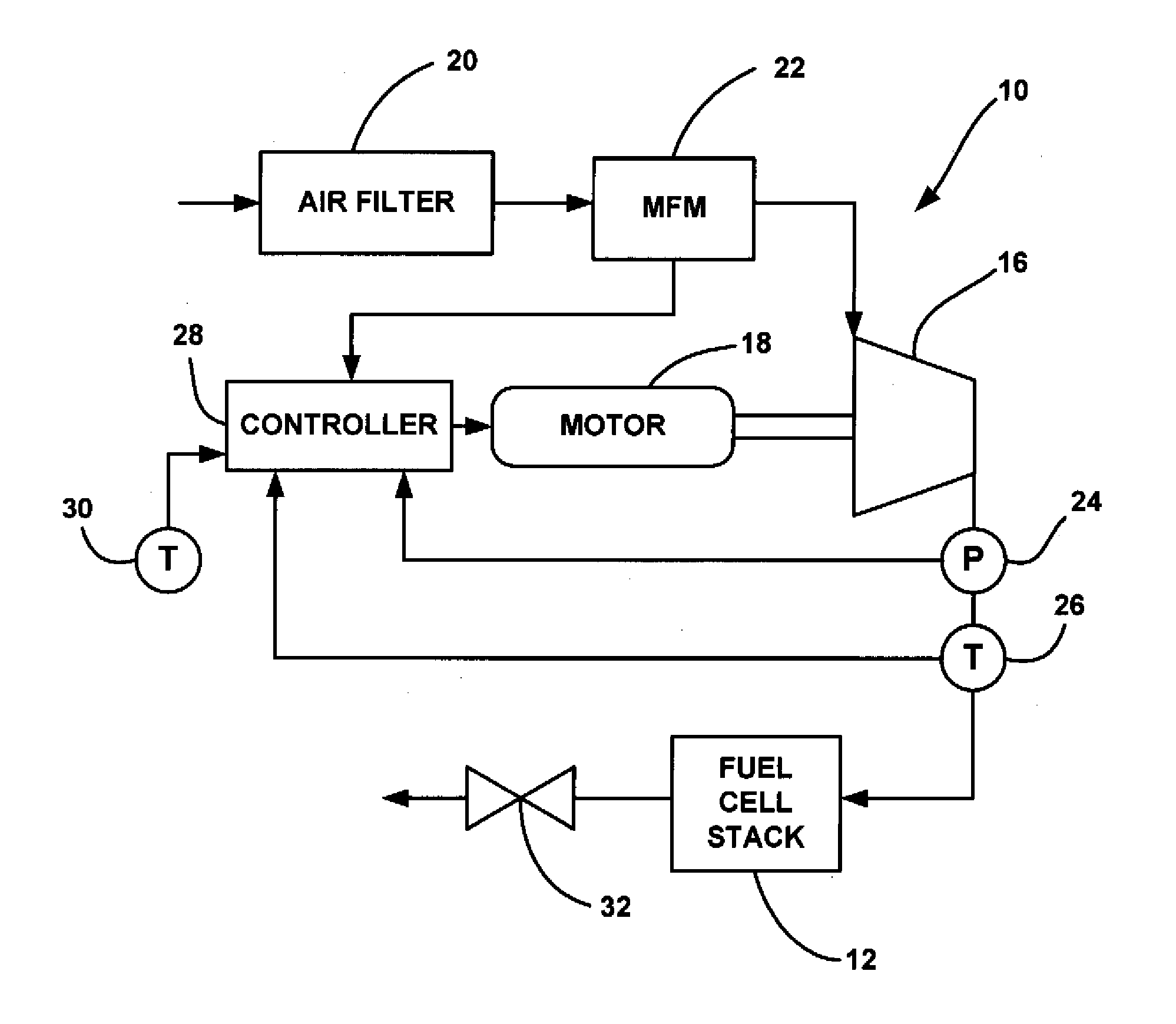
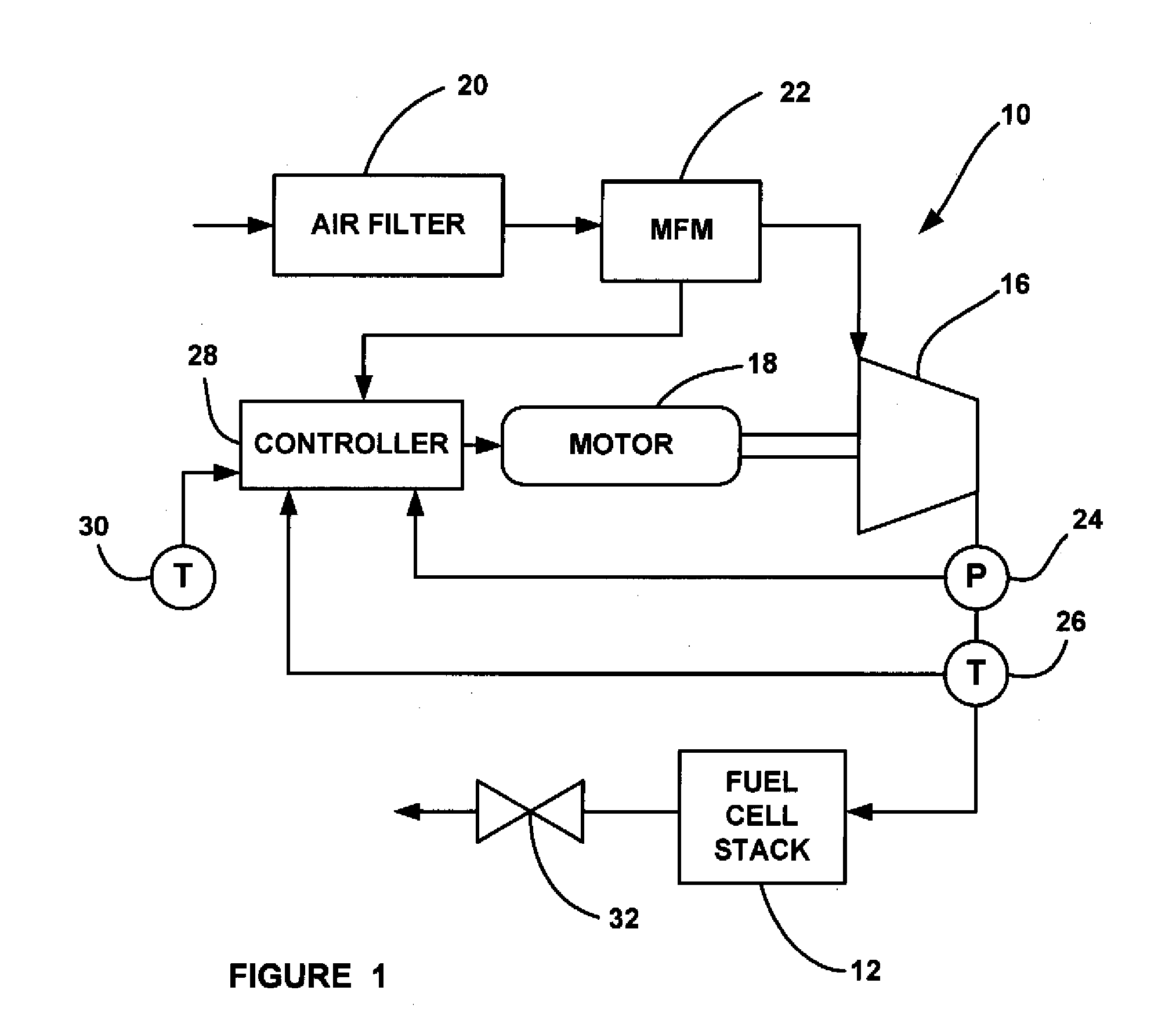
[0015]FIG. 1 is a plan view of a fuel cell system 10 including a fuel cell stack 12. The fuel cell system 10 can be used for any suitable application, such as on a vehicle or as a distributed generation power system. The system 10 includes a turbo-machine compressor 16 that provides charge air to the cathode side of the stack 12. The compressor 16 can be any suitable turbo-machine type compressor, such as a centrifugal, radial, axial, mixed flow, etc., compressor. This type of compressor is desirable in the system 10 because it is low cost and low weight, and operates with low noise as compared to positive displacement compressors, such as twin-screw compressors. The hydr...


PUM


Abstract

A fuel cell system that includes a compressor for providing cathode air to the cathode side of a fuel cell stack and an air filter for filtering the air sent to the compressor to prevent particulates and other contaminants from entering the compressor and the fuel cell stack. The fuel cell system also includes a mass flow meter that measures the flow of air to the compressor and a pressure sensor that measures the pressure of the airflow at the output of the compressor. An electronic compressor map is provided that defines the operating characteristics of the compressor. By knowing the flow through the compressor and the pressure at the outlet of the compressor, an algorithm can determine where on the compressor map the compressor is operating, and from that determine the inlet pressure to the compressor, which in turn shows whether the air filter is clogged or otherwise damaged.

Description

BACKGROUND OF THE INVENTION[0001]1. Field of the Invention[0002]This invention relates generally to a system and method for determining when to replace a compressor air filter in a fuel cell system and, more particularly, to a system and method for determining when to replace a compressor air filter in a fuel cell system that uses a compressor map to determine compressor inlet pressure based on the airflow through the compressor and the compressor discharge pressure.[0003]2. Discussion of the Related Art[0004]Hydrogen is a very attractive fuel because it is clean and can be used to efficiently produce electricity in a fuel cell. A hydrogen fuel cell is an electro-chemical device that includes an anode and a cathode with an electrolyte therebetween. The anode receives hydrogen gas and the cathode receives oxygen or air. The hydrogen gas is dissociated in the anode to generate free protons and electrons. The protons pass through the electrolyte to the cathode. The protons react with t...

Claims


Application Information

Patent Timeline
IPC IPC(8): H01M8/04
CPCH01M8/04201H01M8/04373H01M8/04425Y02E60/50H01M2008/1095H01M2250/20Y02T90/32H01M8/04776Y02T90/40
Inventor RAINVILLE, JOSEPH D.KIRKLIN, MATTHEW C.
Owner GM GLOBAL TECH OPERATIONS LLC
Why Eureka
Eureka Blog
Learn More