
Microfluid system and method to test for target molecules in a biological sample

a microfluidic and biological sample technology, applied in the field of microfluidics, can solve the problems of increasing the difficulty of sample preparation, increasing the limit of the detection system, and not conducting an analysis in serum

Active Publication Date: 2010-06-17
FIO CORP
View PDF101 Cites 16 Cited by
  • Summary
  • Abstract
  • Description
  • Claims
  • Application Information

AI Technical Summary

Benefits of technology

[0034]According to an aspect of one preferred embodiment of the invention, passage of the test molecules through the aforesaid at least one of the sample channels is facilitated by electrokinetic flow.
[0072]According to an aspect of one preferred embodiment of the invention, in the sample focusing step, passage of the single-file stream of the test molecules through the aforesaid at least one of the sample channels is facilitated by electrokinetic flow.

Problems solved by technology

One of the challenges created by these advances is developing practical uses for discovered scientific phenomena.
Furthermore, the analysis was not conducted in serum, which could decrease sensitivity because of interference from blood components [E. D. Goluch et al., Lab Chip, 6, 1293 (2006)].
Furthermore, in order to achieve single conjugate detection, the concentration of the sample was reduced to the femtomolar level, increasing the difficulty of sample preparation and the limits on the detection system.

Method used


Image

  • Microfluid system and method to test for target molecules in a biological sample
  • Microfluid system and method to test for target molecules in a biological sample
  • Microfluid system and method to test for target molecules in a biological sample

Examples


Embodiment Construction

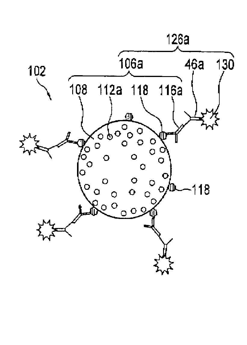
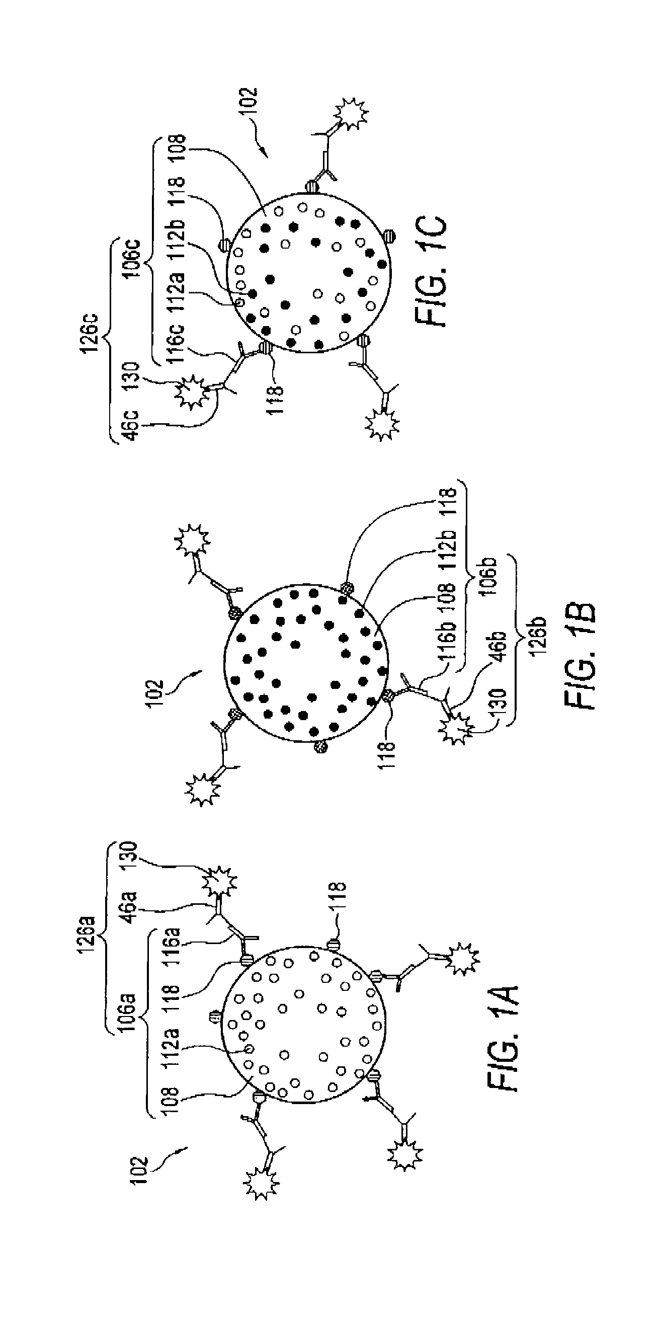
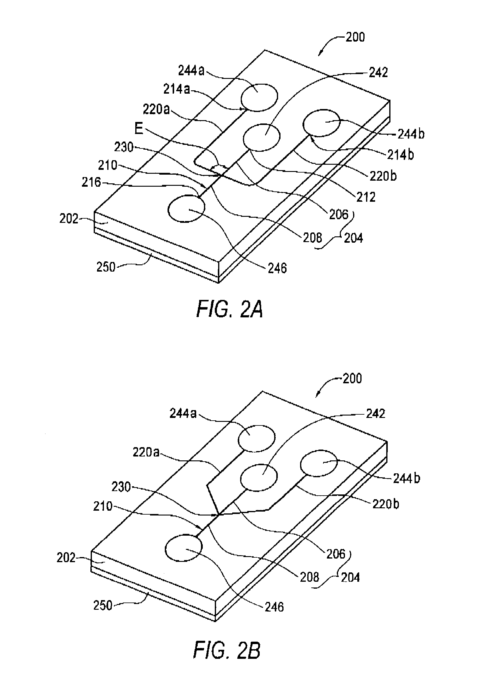
[0122]Referring now to FIGS. 1A through 4G, there is shown a test system 100 according to a preferred embodiment of the present invention. The test system 100 is for use with a buffer 50 to test for the presence of target molecules 46a, 46b, 46c (46a-c) of one or more target types in a biological test sample 40. The test system 100 preferably includes a first set of test molecules 102, a microfluidic chip 200, an irradiating device 300, and a detection device 400. The test system 100 also preferably includes a housing 500 encasing the irradiating device 300 and the detection device 400, with housing 500 being sized and adapted for portable, hand-held, and point-of-care diagnostic use.

[0123]Introduction to the System

[0124]Preferably, the first set of test molecules 102 may include (i) detection molecules 106a, 106b, 106c (106a-c) and (ii) conjugates 126a, 126b, 126c of the detection molecules 106a-c and the target molecules 46a-c, if present in the test sample 40.

[0125]As best seen i...


PUM

PropertyMeasurementUnit
sizeaaaaaaaaaa
sizeaaaaaaaaaa
sizeaaaaaaaaaa

Abstract

A system and method to test for the presence of target molecules in a biological test sample includes test molecules, a microfluidic chip, and irradiating and detection devices. The test molecules include bio-recognition molecules conjugable with the target molecules, and the corresponding conjugates. The microfluidic chip includes sample channels and flow focusing channels adjoining the sample channels. A buffer exiting from the focusing channels directs a single-file stream of the test molecules through one of the sample channels. The irradiating device delivers radiation for absorption by the test molecules in the single-file stream. After absorption, the test molecules emit fluorescence of a distinct fluorescent spectrum for each of the conjugates. The detection device monitors identifies the presence of the conjugates by monitoring for the distinct fluorescent spectrum. Thus, the test system and method identifies the presence of the target molecules in the test sample.

Description

FIELD OF THE INVENTION[0001]The present invention relates to the field of microfluidics. In particular, it relates to a microfluidic channel structure for reading fluorescent microbeads.BACKGROUND OF THE INVENTION[0002]The last decade has seen many advances in the fields of microtechnology and nanotechnology. One of the challenges created by these advances is developing practical uses for discovered scientific phenomena.[0003]A few published reports of attempts to integrate nano- with microtechnology for biomolecular or viral detection have been described [W. Liu et al., Lab Chip, 5, 1327 (2005); K. Yun, D. Lee, H. Kim, E. Yoon, Meas. Sci. Technol., 17, 3178 (2006); J. Steigert et al., JALA, 10, 331 (2005)]. In these studies, the researchers used a combination of nanoparticles, microbeads, and microfluidics for detection. In all cases, the detection sensitivity was lower than desirable for a productive, commercial product. Furthermore, the analysis was not conducted in serum, which ...

Claims


Application Information

Patent Timeline
Patent Type & Authority Applications(United States)
IPC IPC(8): C12Q1/70G01N27/00C12M1/34G01N21/64G01N33/53G01N33/544G01N27/447
CPCB82Y15/00G01N21/645G01N33/54346G01N33/587G01N33/588G01N2021/6421G01N2021/6441G01N33/54366Y02A90/10Y02A50/30
Inventor XIANG, QINGCHAN, WARREN CHE WORKLOSTRANEC, JESSE M.
Owner FIO CORP
Learn More