
Thermal error compensation method for machine tools

a technology of machine tools and error compensation, applied in the direction of heat measurement, program control, instruments, etc., to achieve the effect of improving the machining precision of the machine tool

Active Publication Date: 2010-06-17
IND TECH RES INST
View PDF25 Cites 51 Cited by
  • Summary
  • Abstract
  • Description
  • Claims
  • Application Information

AI Technical Summary

Benefits of technology

[0017]The object of the present invention is to provide a thermal error compensation method for machine tools, capable of taking the geometrical structure and the material of a machine tool into consideration for calculating thermal error compensation values for a machine tool, by that the information relating to the integral structural response of a machine to temperature variation can be obtained basing upon heat sources' temperature detection performed on the machine tool and thus the thermal error model established in the invention can be provided with sufficient information for enabling the same to calculate a precise and reliable thermal error values to be used for improving the machining precision of the machine tool.

Problems solved by technology

In precision machinery processing, machine tool thermal error is the major factor to cause workpiece's error.
Thus, how to control machine tool thermal error becomes essential technique to increase the processing precision and was and still is the key issue of precision machinery development ever since 1960s.
As soon as the thermal state of a machine tool is affected and changed by a heat source, it is more than possible that a certain displacement between the cutting tool tip and workpiece will be caused which is then being referred as thermal error.
However, since the aforesaid method requires to layout eighty thermal sensors on a machine tool, not only such large amount of thermal sensors is not easy to be deployed, but also the operation cost of the aforesaid method is increased and thus the method may not be feasible.
As the temperature information relating to the areas of the machine tool that are not attached by thermal sensors will not be gathered for analysis, the performance of the aforesaid device is overly rely on how much the thermal sensors are disposed on a machine tool and how those thermal sensors are distributed as well.
However, the aforesaid control system is unable to response to the thermal error caused by the interaction between different internal heat sources in a machine tool as the distribution of the internal heat sources of the machine tool can be varied with the changing of feed-driving condition of the machine tool.
However, similarly to the previous-described prior arts, the precision of the compensation system in this U.S. patent still highly rely on how the thermal sensors is distributed on the machine tool, and moreover, it is not considering the affection of the machine tool's geometrical structure, the relative positions of the components in the machine tool, and the interaction between heat sources of the machine tool, and so on.
However, the aforesaid prior arts have the following shortcomings:(1) lacking the physical information relating to the integral structure of a machine tool, because of that the thermal error model can not response to the affection resulting from the geometrical shape and material of the machine tool since the prior arts only use the temperature information detected from the significant nodes on the machine tool to establish its thermal error model while the greater part of the thermal error of a machine tool is resulting from the affection of temperature variation upon the integral structure of the machine tool;(2) not considering the interaction between heat sources of a machine tool, that is because that the relative positions of the heat sources on a machine tool can be varied with the changing of feed-driving condition of the machine tool, and thus the thermal error caused by the interaction between heat sources whose positions are not fixed may be a difficult task since there may be different thermal errors even when the prior arts detect the same temperature information which can only be prevented in the prior art by a large number of experiments for achieving an optimal distribution of thermal sensors;(3) only providing a limited amount of temperature information for the thermal error model, because of that the precision and reliability of the thermal error model can be greatly affected by the layout of the thermal sensors as the parameters required for calculating the thermal error compensation values in the thermal error model are gathered and based upon temperatures detected from those thermal sensors distributed on a machine tool, so that the more sensors used, the more precise understanding regarding to the overall temperature information of a machine tool will have, but with increasing cost;(4) achieving a thermal error model of poor precision and reliability, which is directly consequent from the aforesaid three shortcomings.

Method used


Image

  • Thermal error compensation method for machine tools
  • Thermal error compensation method for machine tools
  • Thermal error compensation method for machine tools

Examples


Embodiment Construction

[0026]For your esteemed members of reviewing committee to further understand and recognize the fulfilled functions and structural characteristics of the invention, several exemplary embodiments cooperating with detailed description are presented as the follows.

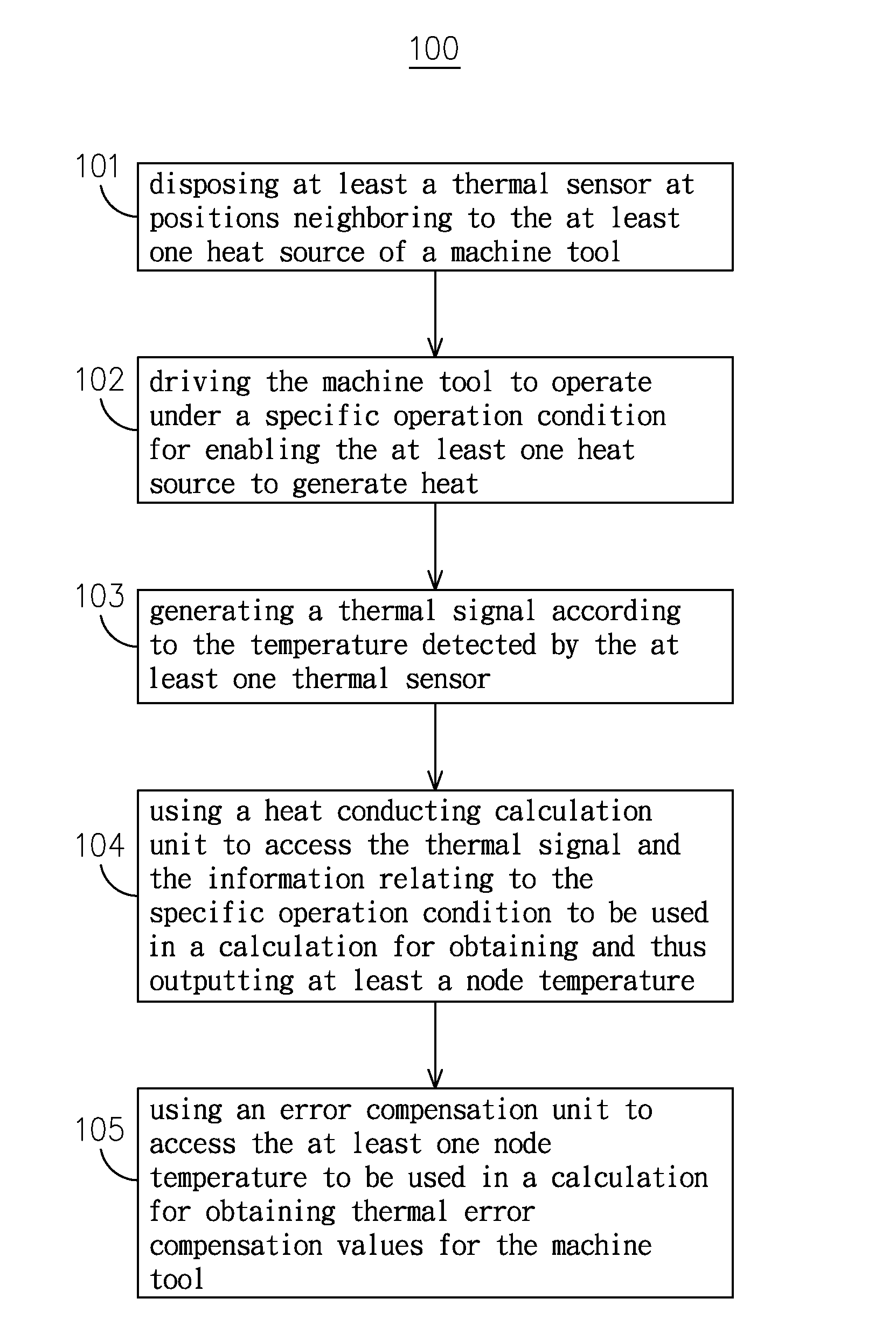
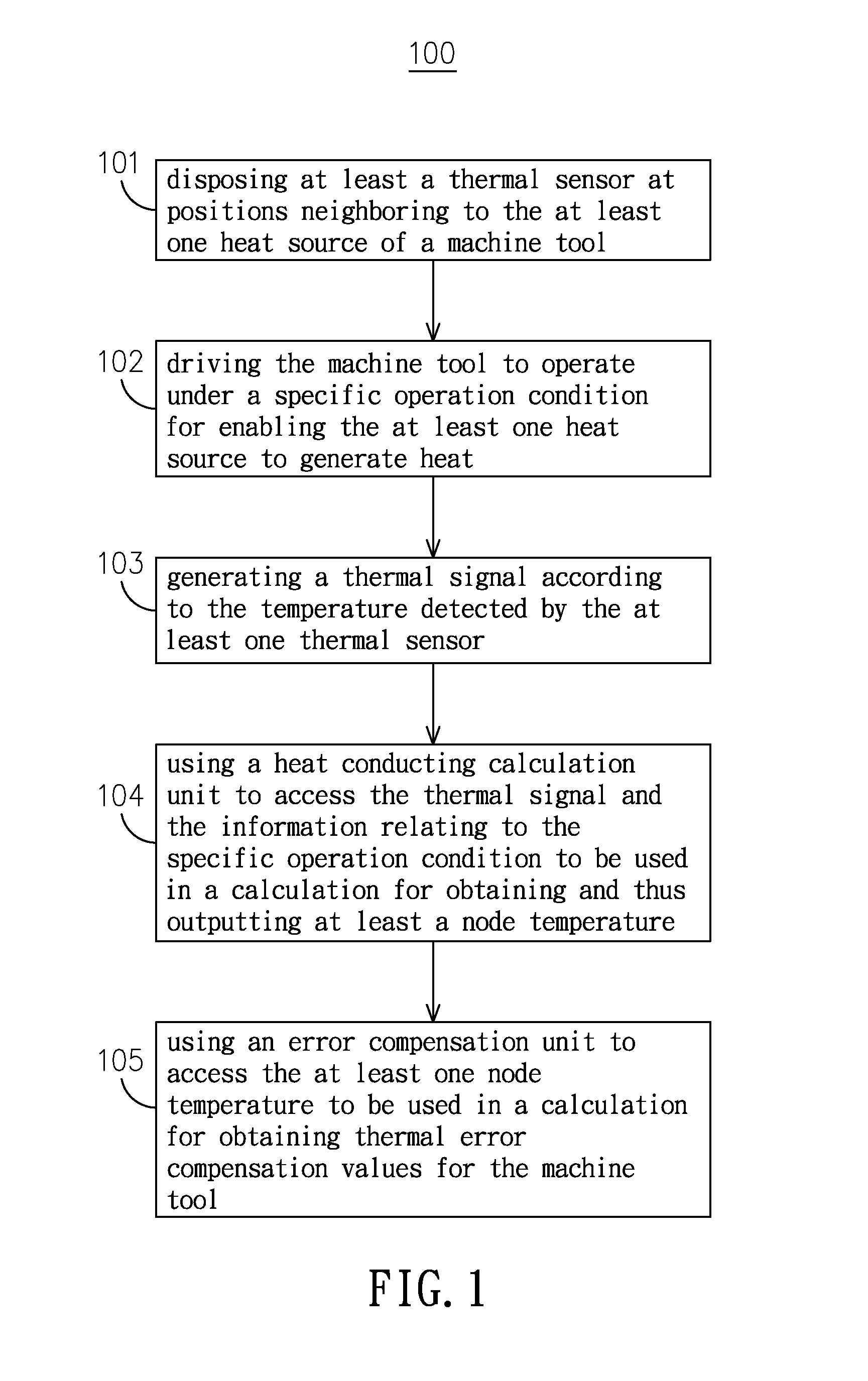
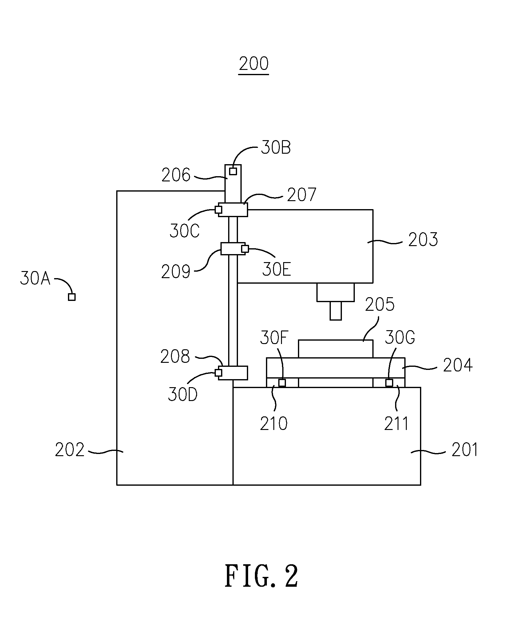
[0027]Please refer to FIG. 1, which is a flow chart depicting the steps of a thermal error compensation method for machine tools according to the present invention. As shown in FIG. 1, the thermal error compensation method for machine tools 100 of the invention starts from the step 101. At step 101, there is at least a thermal sensor being disposed at positions neighboring to the at least one heat source of a machine tool; and then the flow proceeds to step 102. As shown in FIG. 2, the machine tool 200, being composed of a base 201, a column 202, a spindle headstock 203, a saddle 204 and a table 205, has thermal sensors, e.g. 30A˜30G, mounted thereon at positions neighboring to its heat sources in respective. Generally, the di...


PUM


Abstract

A thermal error compensation method for machine tools is disclosed, which comprises the steps of: disposing at least a thermal sensor at positions neighboring to the at least one heat source of a machine tool; driving the machine tool to operate under a specific operation condition for enabling the at least one heat source to generate heat; generating a thermal signal according to the temperature detected by the at least one thermal sensor; using a heat conducting calculation unit to access the thermal signal and the information relating to the specific operation condition to be used in a calculation for obtaining and thus outputting at least a node temperature; and using an error compensation unit to access the at least one node temperature to be used in a calculation for obtaining thermal error compensation values for the machine tool.

Description

FIELD OF THE INVENTION[0001]The present invention relates to a thermal error compensation method for machine tools, and more particularly, to a method capable of taking the geometrical structure and the material of a machine tool into consideration for calculating thermal error compensation values of the machine tool by the use of a heat conducting calculation unit and an error compensation unit.BACKGROUND OF THE INVENTION[0002]In precision machinery processing, machine tool thermal error is the major factor to cause workpiece's error. Thus, how to control machine tool thermal error becomes essential technique to increase the processing precision and was and still is the key issue of precision machinery development ever since 1960s. The reduction of thermal error in machine tools for the purpose of processing precision and stability improvement is mostly approached by the development of a systematic logical machine tool design or a thermal error compensation method. Nevertheless, de...

Claims


Application Information

Patent Timeline
IPC IPC(8): G05B19/404G05B13/04G06G7/56
CPCG05B19/404G05B2219/49206
Inventor OU, FENG-MINGWU, JAMES SHIH-SHYN
Owner IND TECH RES INST
Features
  • Generate Ideas
  • Intellectual Property
  • Life Sciences
  • Materials
  • Tech Scout
  • Unparalleled Data Quality
  • Higher Quality Content
  • 60% Fewer Hallucinations
Learn More