Process and Device for Generating Gas From Carbonaceous Material

a carbonaceous material and gas technology, applied in the direction of dynamo-electric machines, combustible gas production, gasification process details, etc., can solve the problem of probable gas emission, and achieve the effect of increasing the overall efficiency of the device for generating electrical energy, low vibration, and low noise load

Inactive Publication Date: 2010-06-24
ME MUNSTERLAND ENERGY
View PDF11 Cites 19 Cited by
  • Summary
  • Abstract
  • Description
  • Claims
  • Application Information

AI Technical Summary

Benefits of technology

[0008]By coupling energy into the carbonaceous material via microwaves, the carbonaceous material is completely penetrated with little effort and is rapidly heated from the inside to the outside. In addition, with carbonaceous material containing moisture, it is sufficiently dried and the moisture is converted into water steam, which is then available as an oxidant during the gasification. Because the carbonaceous material is heated from the inside to the outside, combustion is suppressed and instead the carbonaceous material is pyrolytically cleaved into volatile carbon compounds and nonvolatile carbon compounds having shorter carbon chains. The carbonaceous material may be preheated or heated after or in parallel to the microwave radiation by conventional heating means from the outside to the inside. The time required for the most complete possible pyrolysis is reduced and the energy balance of the overall process is improved as a whole by the heat introduction occurring from the inside to the outside and the outside to the inside. The pyrolysis products are used hereafter as educts for the gasification, which runs more rapidly and efficiently because of the pyrolysis which has already been at least partially performed.
[0028]The hot gas burner is preferably implemented as a pore burner. This has the advantage that the permitted intake temperature of the gas is still so high that interfering contaminants such as tar are still in the volatile state. The effort for cleaning the generated gas may thus be reduced to a minimum, which allows an especially compact and energy-efficient construction of the device for generating electrical energy.

Problems solved by technology

The higher the temperature, the lower the probability that the resulting gas will still contain toxic or carcinogenic components such as dioxin or tar.

Method used


Image

  • Process and Device for Generating Gas From Carbonaceous Material
  • Process and Device for Generating Gas From Carbonaceous Material
  • Process and Device for Generating Gas From Carbonaceous Material

Examples


Embodiment Construction

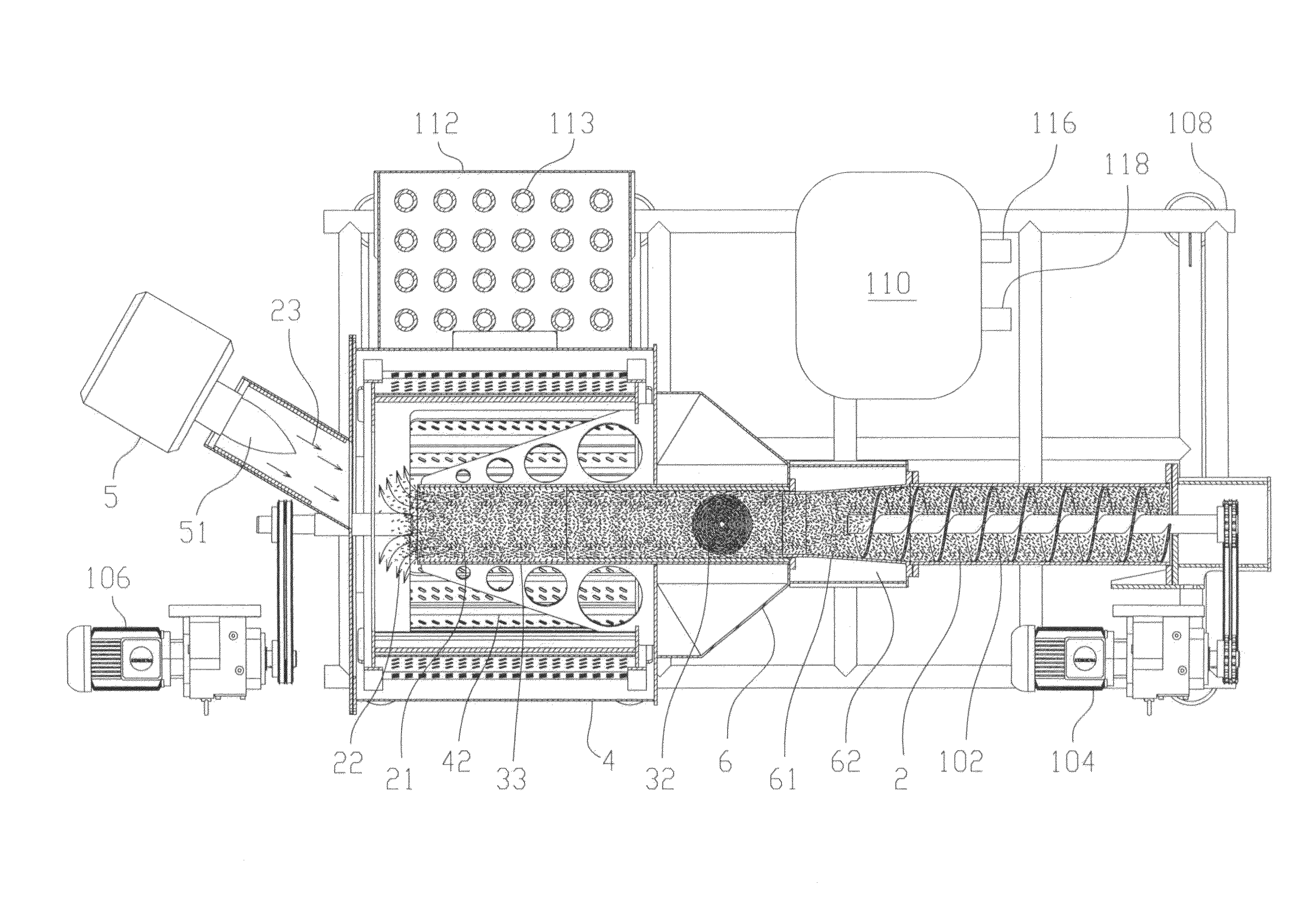
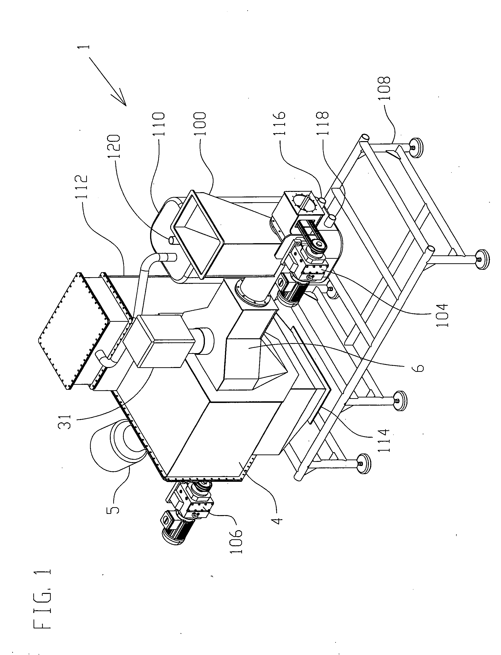
[0048]FIG. 1 shows a gas generator 1 on a facility 108, which is designed for a power of approximately 100 kWel (net). The starting material may be industrial waste or household waste or biomass based on renewable raw materials, such as garden waste, wood chips, preferably of a grain size of approximately 6-20 mm, sawdust, pellets, peelings, husks, or straw. Fossil fuels may also be gasified in the gas generator.

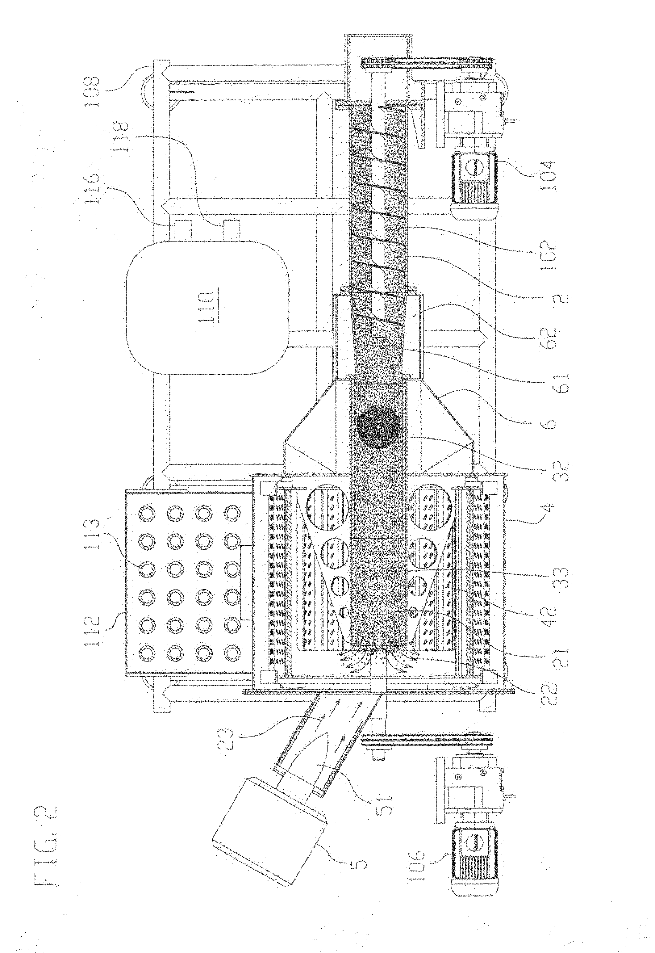
[0049]The carbonaceous material is poured in via the funnel 100. The carbonaceous material 2 may already be preheated therein to approximately 60°-80° C. using the waste heat of a gas cooler 10 in the form of a heat exchanger, possibly combined with a gas washer (see also reference numeral 201, FIG. 7).

[0050]The carbonaceous material 2 is conveyed further into a secondary reactor 6 with the aid of transport screw 102 (see also FIGS. 2, 3) having drive 104. The carbonaceous material 2 is heated to approximately 400-500° C. therein. This is predominantly performed via microwav...


PUM

PropertyMeasurementUnit
temperaturesaaaaaaaaaa
temperatureaaaaaaaaaa

Abstract

To gasify carbonaceous material into gas containing CO and H2, the drying and / or the heating and the pyrolysis of the carbonaceous material are performed using microwave irradiation and thermal irradiation and the pyrolysis products and / or the carbonaceous material are then gasified. For this purpose the carbonaceous material is irradiated in a microwave station with a heating unit, and then passed on into a reactor for gasification. The gasification occurs with the aid of a water-steam plasma source.

Description

FIELD OF THE INVENTION[0001]The present invention relates to a method and a device for generating gas containing CO and H2 from carbonaceous material. Furthermore, the invention relates to a device for generating electrical energy using pyrolysis and gasification of carbonaceous materials into gas containing CO and H2 having a gasification reactor, an engine driven with the aid of the gas containing CO and H2, and a power generator driven by the engine.BACKGROUND OF THE INVENTION[0002]With the background of decreasing resources of fossil fuels, decentralized power supply on the basis of waste or biomass from renewable raw materials receives ever more significance. Heat is generated in biomass or waste combustion, which may be used for heating buildings or water, for example. In gasification, combustion gas which may be used in engines for power generation is generated in addition to heat.[0003]Gasification is generally executed in multiple steps: drying / heating for preparation, pyro...

Claims


Application Information

Patent Timeline
Patent Type & Authority Applications(United States)
IPC IPC(8): F02B43/00B01J19/12H02K7/18
CPCC10B19/00C10J3/66C10J2200/09C10J2300/1634C10J2300/0973C10J2300/1223C10J2300/1238C10J2200/158
Inventor KEMPER, JORGLOHMANN, FRANK
Owner ME MUNSTERLAND ENERGY
Why Eureka
Try Eureka