Thermally insulated pipe for use at very high temperatures

a technology of thermal insulation pipe and high temperature, applied in the direction of thermal insulation, rigid pipes, pipes, etc., can solve the problems of inorganic insulation materials suffering a number of very significant drawbacks, inorganic insulation material soddenness, and service temperature limitations of polymeric foams such as polyurethane (puf) and polyisocyanura

Inactive Publication Date: 2010-06-24
SHAWCOR LTD
View PDF15 Cites 62 Cited by
  • Summary
  • Abstract
  • Description
  • Claims
  • Application Information

AI Technical Summary

Benefits of technology

[0010]In one aspect, the present invention provides an insulated pipe comprising a pipe and a composite insulation system, said composite insulation system comprising: (a) a first insulation layer comprising a first insulation material having a thermal conductivity k-factor value of less than 0.023 W/m-K at 38° C.; (b) at least one additional insulation layer comprising an insulation material having a thermal conductivity k-factor greater

Problems solved by technology

Service temperature limitations of polymeric foams such as polyurethane (PUF) and polyisocyanurate (PIF) materials for continuous long-term use, however, are limited to approximately 150° C. There is thus a need for thermal insulation systems that can operate at temperatures exceeding 150° C. while retaining or exceeding the thermal insulation efficiency of existing closed-cell foam systems.
However, such inorganic insulation materials suffer a number of very significant drawbacks.
If such materials come into contact with water, such as from a leak in the outer jacket protecting the insulation from the elements, the inorganic insulation will become sodden and it will no longer act as a thermal insulation.
Glass foam, which is primarily closed cell and therefore less inclined to absorb water, is extremely abrasive, and will destroy any anti-corrosion coating applied to protect the pipe as a consequence of the

Method used


Image

  • Thermally insulated pipe for use at very high temperatures
  • Thermally insulated pipe for use at very high temperatures
  • Thermally insulated pipe for use at very high temperatures

Examples


Embodiment Construction

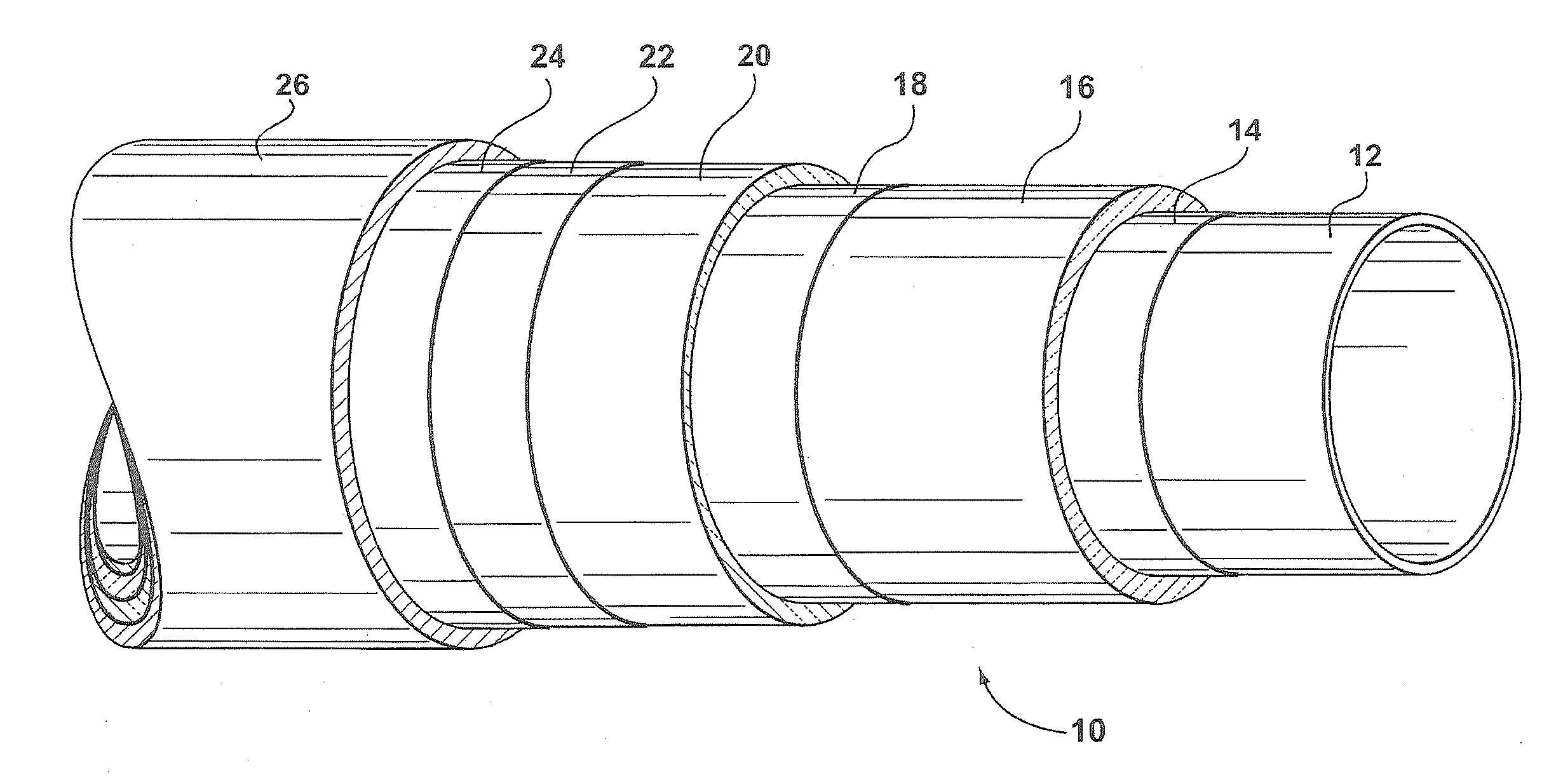
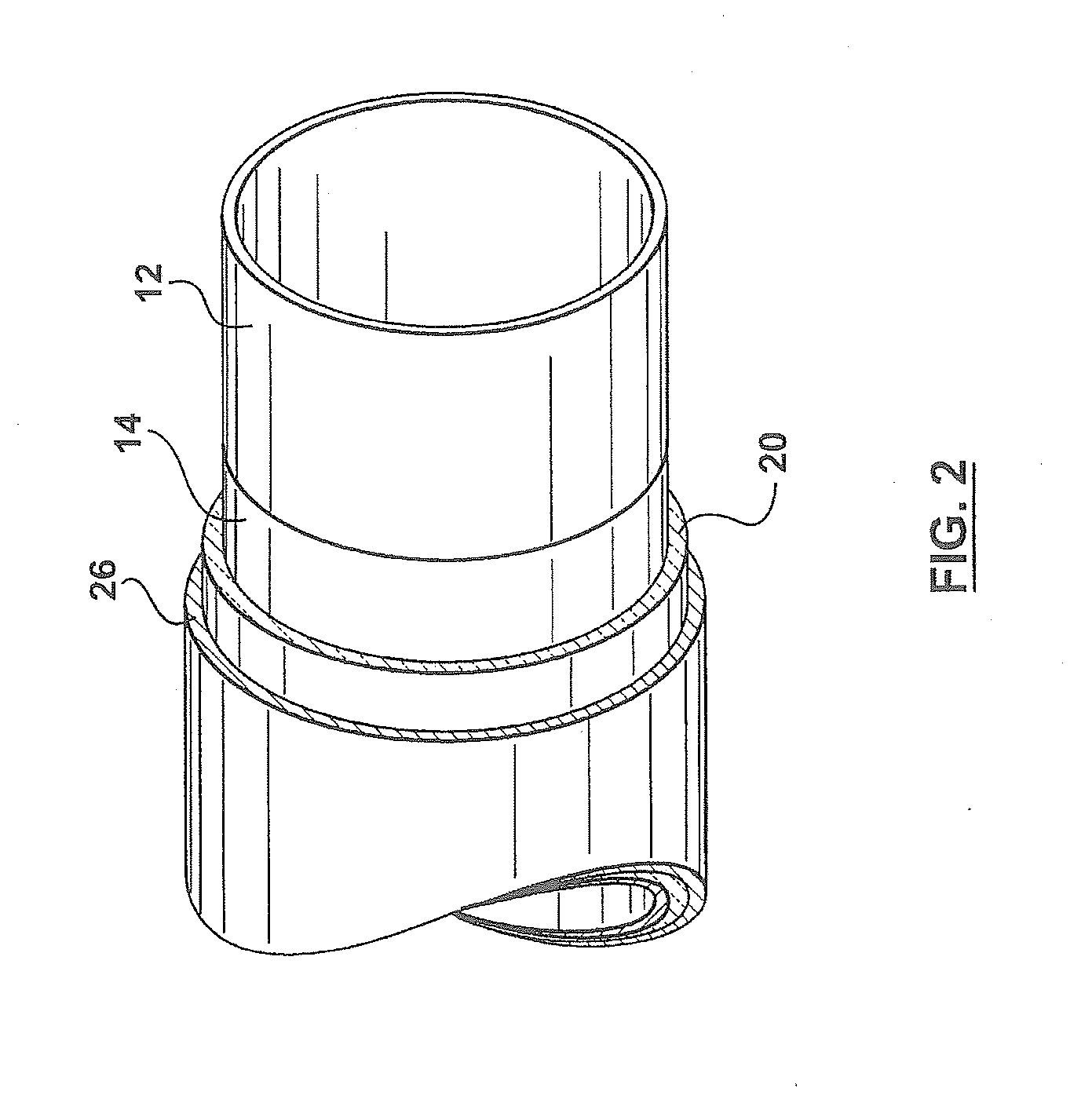
[0061]The present invention provides a thermally insulated pipe comprising a pipe and a composite insulation system, particularly suited for use at very high operating temperatures (i.e. greater 150° C.). The composite insulation system is formed in situ by application of the first insulation layer to the exterior surface of the pipe followed by application of an additional insulation layer to surround said first insulation layer. Application of at least one of the insulation layers is performed in a continuous manner.

[0062]As used herein the term “continuous manner” in the context of the application of insulation materials or layers thereof, refers to any suitable method of application capable of applying the insulation materials or layers thereof onto a length of pipe which moves in relation to a station applying or delivering said insulation layer. The particular method of continuous application will depend on the choice of insulation materials. For example, wherein the insulatio...


PUM


Abstract

The present invention provides an insulated pipe comprising a pipe and a composite insulation system, said composite insulation system comprising: (a) a first insulation layer comprising a first insulation material having a thermal conductivity k-factor value of less than 0.023 W/m-K at 38° C.; and (b) at least one additional insulation layer comprising an insulation material having a thermal conductivity k-factor greater than that of the first insulation material and a maximum operating temperature limit less than that of the first insulation layer. The composite insulation system is bonded to an exterior surface of the pipe with the first insulation layer facing towards said exterior surface of the pipe. At least one of said first insulation layer or said at least one additional layer extends continuously about the exterior surface of the pipe. The present invention further provides an insulated pipe for use in an undersea pipeline and an insulated pipe for use in a subterranean pipeline.

Description

FIELD OF INVENTION[0001]The present invention relates to insulated pipes comprising a thermal insulation system particularly for use at very high operating temperatures and having very low heat loss and insulation thickness in comparison with conventional high temperature insulation systems used with pipes.BACKGROUND[0002]Structures used to store or transport materials at temperatures exceeding the temperature of the surroundings are often coated with materials that retard the flow of heat to the surroundings. Pipelines and other structures employed in transporting oil, natural gas, petroleum products and other products are often insulated to maintain a temperature such that the contents remain sufficiently warm to be flowable, or to prevent the precipitation of components such as wax (from crude oil) or hydrogen sulphide hydrates (from raw gas). Pipelines are also used to transport heated water for use in district heating, in which case it is important to minimize the loss of store...

Claims


Application Information

Patent Timeline
IPC IPC(8): F16L9/14F16L59/14
CPCF16L59/143F16L59/029
Inventor BATALLAS, MAURICESINGH, PETER
Owner SHAWCOR LTD
Why Eureka
Try Eureka