Process for energy beam solid-state metallurgical bonding of wires having two or more flat surfaces

a technology of solid-state metallurgical bonding and energy beam, which is applied in the direction of welding/cutting media/materials, manufacturing tools, solvents, etc., can solve the problems that single crystal alloys cannot tolerate repairs, and achieve strong wave-shape interface morphology, high cost, and high strength

Inactive Publication Date: 2010-06-24
RABINOVICH JOSHUA E
View PDF50 Cites 16 Cited by
  • Summary
  • Abstract
  • Description
  • Claims
  • Application Information

AI Technical Summary

Benefits of technology

[0028]The disclosed process allows for a solid-state welding on flat and curved surfaces with extremely strong wave-shape interface morphology, reminiscent to the explosion welding but without its high cost, component shape limitations, and safety disadvantages. The process allows for strong, metallurgical bond coating of components made out of inexpensive, light weight metals, such as aluminum alloy, with high strength alloys thus transforming these components into stronger metal-composite components without loosing their light weight value.
[0029]Yet another revolutionary capability of the disclosed process is in restoration of high value aircraft jet engine components, such as turbine blades, made out of single crystal alloys. Single crystal alloys cannot tolerate repairs with temperatures reaching liquefaction levels; they re-crystallize and loose their single crystal structure and fatigue strength qualities. The disclosed process can restore these extremely expensive components by keeping the temperatures of the parent material below the material's liquefaction point, thus maintaining the single crystal advantages.
[0030]In practicing this invention, a continuously fed flat wire is delivered to a substrate such that the bottom of the wire flat surface(s) is tangential to the substrate such that the contact of the wire with the substrate constitutes substantially a surface(s), allowing efficient conduction of the energy beam produced stress and thermal waves from the wire to the substrate. The flat wire surface conforms to the surface of the substrate and provides repeatable and reliable contact during coating process.

Problems solved by technology

Single crystal alloys cannot tolerate repairs with temperatures reaching liquefaction levels; they re-crystallize and loose their single crystal structure and fatigue strength qualities.

Method used


Image

  • Process for energy beam solid-state metallurgical bonding of wires having two or more flat surfaces
  • Process for energy beam solid-state metallurgical bonding of wires having two or more flat surfaces

Examples


Embodiment Construction

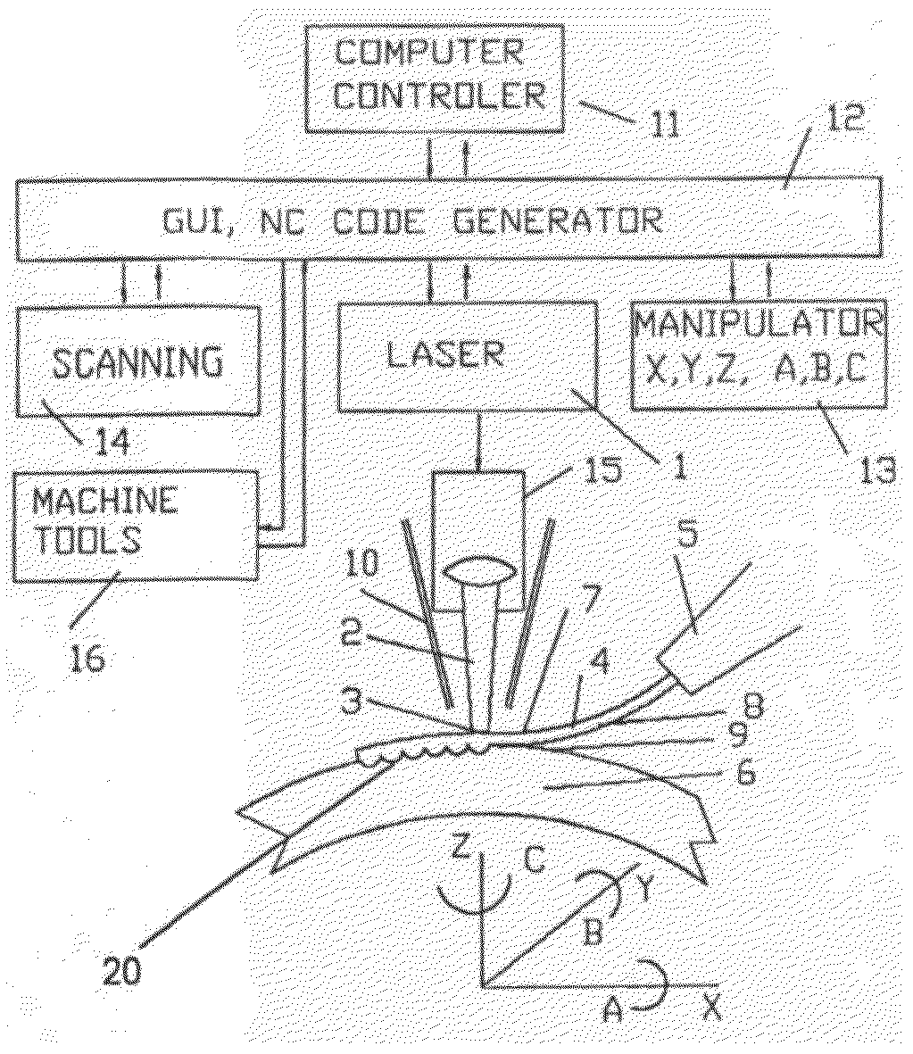
[0041]The present invention disclosed a process for energy beam assisted solid-state metallurgical bonding of a wire with two or more flat surfaces, to a substrate, for the purpose of substrate coating, 3-Dimensional component buildup, restoration, and component surface improvement. An energy beam, (for example Laser or Electron Beam), preferably pulsed, is used. For the purpose of this description, a laser 1 is used and its focused beam 2 as shown in the block diagram of FIG. 1. The laser beam focused spot 3 of an adjustable small diameter is directed to the top surface 7 of the wire 4.

[0042]A continuously fed flat wire 4 is dispensed from a wire nozzle 5 and delivered to a substrate 6 such that the bottom of the wire flat surface(s) is tangential to the substrate 6 top surface 9. The contact of the wire with the substrate constitutes substantially a surface(s), thus allowing efficient conduction of the laser beam produced stress and thermal waves from the wire to the substrate. Th...


PUM

PropertyMeasurementUnit
velocitiesaaaaaaaaaa
energyaaaaaaaaaa
power densitiesaaaaaaaaaa

Abstract

An energy beam assisted solid-state welding welds a wire material to a substrate. A wire of coating or repairing material is placed in contact with a surface or surfaces of a substrate. A beam is directed into an outer flat surface of the wire, which heats the wire through flat outer surface of the wire with beam energy. Beam energy produces compression stress-waves that drive molecules of the material flat wire into a surface of the substrate, joining the material and the substrate with strong wave shaped interfaces.

Description

[0001]This application claims the benefit of U.S. Provisional Application No. 61 / 198,203, filed Nov. 4, 2008, which is hereby incorporated by reference in its entirety.BACKGROUND OF THE INVENTION[0002]The present invention generally relates to the field of materials deposition for a component fabrication, restoration, and surface improvement and more particularly, is directed to a process and apparatus for coating or cladding a layer or layers of metal and non-metal materials onto substrates of dissimilar materials.[0003]There are variety of methods known in the prior art for coating or cladding a layer of dissimilar material onto a substrate. Some examples of the known methods that produce enhanced bonding between the coating and the substrate as follows:[0004]1. Thermal Spray processes,[0005]2. Conventional Arc Welding,[0006]3. Laser and Electron Beam metal deposition,[0007]4. Large Scale Explosion Welding and Micro-explosion Welding.[0008]The terms “coating” and “cladding” althou...

Claims


Application Information

Patent Timeline
Patent Type & Authority Applications(United States)
IPC IPC(8): B23K15/00B23K26/20
CPCB23K15/0086B23K26/063B23K26/34B23K26/3206B23K26/324B23K26/345B23K35/0272B23K35/38B23K35/383B23K35/0227B23K35/0244B23K35/0255B23K35/0261B23K35/325B23K26/0622B23K26/342B33Y30/00
Inventor RABINOVICH, JOSHUA E.
Owner RABINOVICH JOSHUA E
Why Eureka
Try Eureka