Focused ion beam apparatus, sample processing method using the same, and computer program for focused ion beam processing

Active Publication Date: 2010-06-24
HITACHI HIGH TECH SCI CORP
View PDF3 Cites 1 Cited by
  • Summary
  • Abstract
  • Description
  • Claims
  • Application Information

AI Technical Summary

Benefits of technology

[0017]In this configuration, the dose amount of the ion beam becomes constant and the degree of processing also become

Problems solved by technology

However, when the image data including the pixels are reduced in scale on the sample image, the number of pixels is reduced according to the ratio of scale reduction of the image data, and hence the image data is deteriorated in finesse of resolution.
In this case, since the position to be irradiated with the focused ion beam is reduced,

Method used


Image

  • Focused ion beam apparatus, sample processing method using the same, and computer program for focused ion beam processing
  • Focused ion beam apparatus, sample processing method using the same, and computer program for focused ion beam processing
  • Focused ion beam apparatus, sample processing method using the same, and computer program for focused ion beam processing

Examples


Example

[0031]Referring now to the drawings, embodiments of the invention will be described.

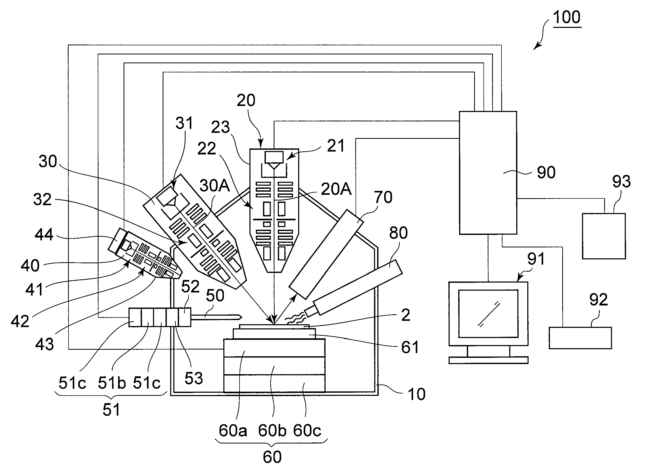
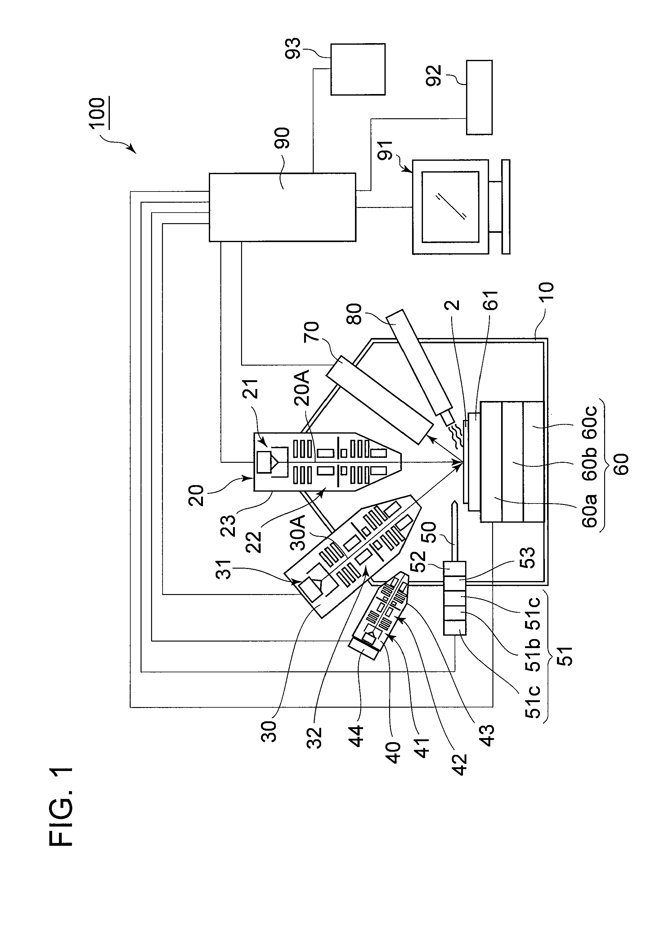
[0032]FIG. 1 is a block diagram showing an entire configuration of a focused ion beam apparatus 100 according to an embodiment of the invention. In FIG. 1, the focused ion beam apparatus 100 includes a vacuum chamber 10, an ion beam irradiating system (“focused ion beam irradiating mechanism” in Claims) 20, an electron beam irradiating system 30, an argon ion beam irradiating system 40, a nanoforceps 50, a sample stage 60, a secondary charged electron detector (“detector” in Claims) 70, a gas gun 80, and a control unit 90. The interior of the vacuum chamber 10 is decompressed to a predetermined degree of vacuum, and part or all of components of the focused ion beam apparatus 100 are arranged in the vacuum chamber 10.

[0033]The sample stage 60 movably supports a sample table 61, and a sample 2 is placed on the sample table 61. Then, the sample stage 60 includes a moving mechanism which allows universal...


PUM


Abstract

A focused ion beam apparatus includes: a focused ion beam irradiating mechanism configured to irradiate a sample with a focused ion beam; a detector configured to detect a secondary charged particle generated by irradiating the sample with the focused beam; an image generating unit configured to generate an sample image of the sample; a processing area setting unit configured to set a processing area image including a plurality of pixels corresponding to positions of irradiation of the focused ion beam on the sample image; a position of irradiation setting unit configured to set coordinates of the pixels included in the processing area image; a beam setting unit configured to set a dose amount of the focused ion beam irradiated from the focused ion beam irradiating mechanism according to intensities; and an interpolating unit configured to perform an interpolating process on the processing area image.

Description

RELATED APPLICATIONS[0001]This application claims priority under 35 U.S.C. §119 to Japanese Patent Application No. 2008-321821 filed on Dec. 18, 2008, the entire content of which is hereby incorporated by reference.BACKGROUND OF THE INVENTION[0002]1. Field of the Invention[0003]The present invention relates to a focused ion beam apparatus configured to process a sample with a focused ion beam, a sample processing method using the same, and a computer program for focused ion beam processing.[0004]2. Description of the Related Art[0005]In the related art, the focused ion beam apparatus has been used for etching a semiconductor device, for example, and obtaining a cross section for observation, or for slicing the sample into a thin piece and fabricating a sample piece for a transmission electron microscope (Japanese Patent No. 2973211). In recent years, there arise needs for processing the sample into complex shapes such as a lens shape or a solder ball shape using the focused ion beam...

Claims


Application Information

Patent Timeline
IPC IPC(8): H01J37/08G21K5/04
CPCH01J37/222H01J37/304H01J37/3056H01J2237/31749H01J2237/24507H01J2237/30416H01J2237/31745H01J2237/221
Inventor SATO, MAKOTOKIYOHARA, MASAHIROTASHIRO, JUNICHI
Owner HITACHI HIGH TECH SCI CORP
Why Eureka
Try Eureka