Tuning-Fork Type Piezoelectric Vibrating Piece and Piezoelectric Device

a piezoelectric and tuning fork technology, applied in the direction of piezoelectric/electrostrictive device details, device material selection, device details, etc., can solve the problems of frequency adjustment that cannot be controlled to a predetermined value, frequency adjustment that cannot be easily adjusted, and collision of tuning portions, etc., to achieve excellent characteristics and suppress the degradation of ci value

Inactive Publication Date: 2010-06-24
NIHON DEMPA KOGYO CO LTD
View PDF10 Cites 37 Cited by
  • Summary
  • Abstract
  • Description
  • Claims
  • Application Information

AI Technical Summary

Benefits of technology

[0021]A piezoelectric vibrating piece according to the present disclosure suppresses degradation of CI value (crystal impedance value) even after miniaturized and also has excellent characteristics. A piezoelectric device using this piezoelectric vibrating piece enables to meet a requirement of miniaturization.

Problems solved by technology

But, the area of film may be small and frequency adjustment amount on the controlling film also becomes small so that the frequency may not be controlled to a predetermined value.
If the frequency of a tuning-fork type piezoelectric vibrating piece is not within a designated value, the metal film of the tuning portion for frequency adjustment is trimmed, but more miniaturized tuning-fork type piezoelectric vibrating piece has a smaller tuning portion so that the frequency adjustment may not perform well.
When the width of tuning portion for frequency adjustment is formed wider, the frequency adjustable range can be larger, but it may also cause a collision of the tuning portions.

Method used


Image

  • Tuning-Fork Type Piezoelectric Vibrating Piece and Piezoelectric Device
  • Tuning-Fork Type Piezoelectric Vibrating Piece and Piezoelectric Device
  • Tuning-Fork Type Piezoelectric Vibrating Piece and Piezoelectric Device

Examples


first embodiment

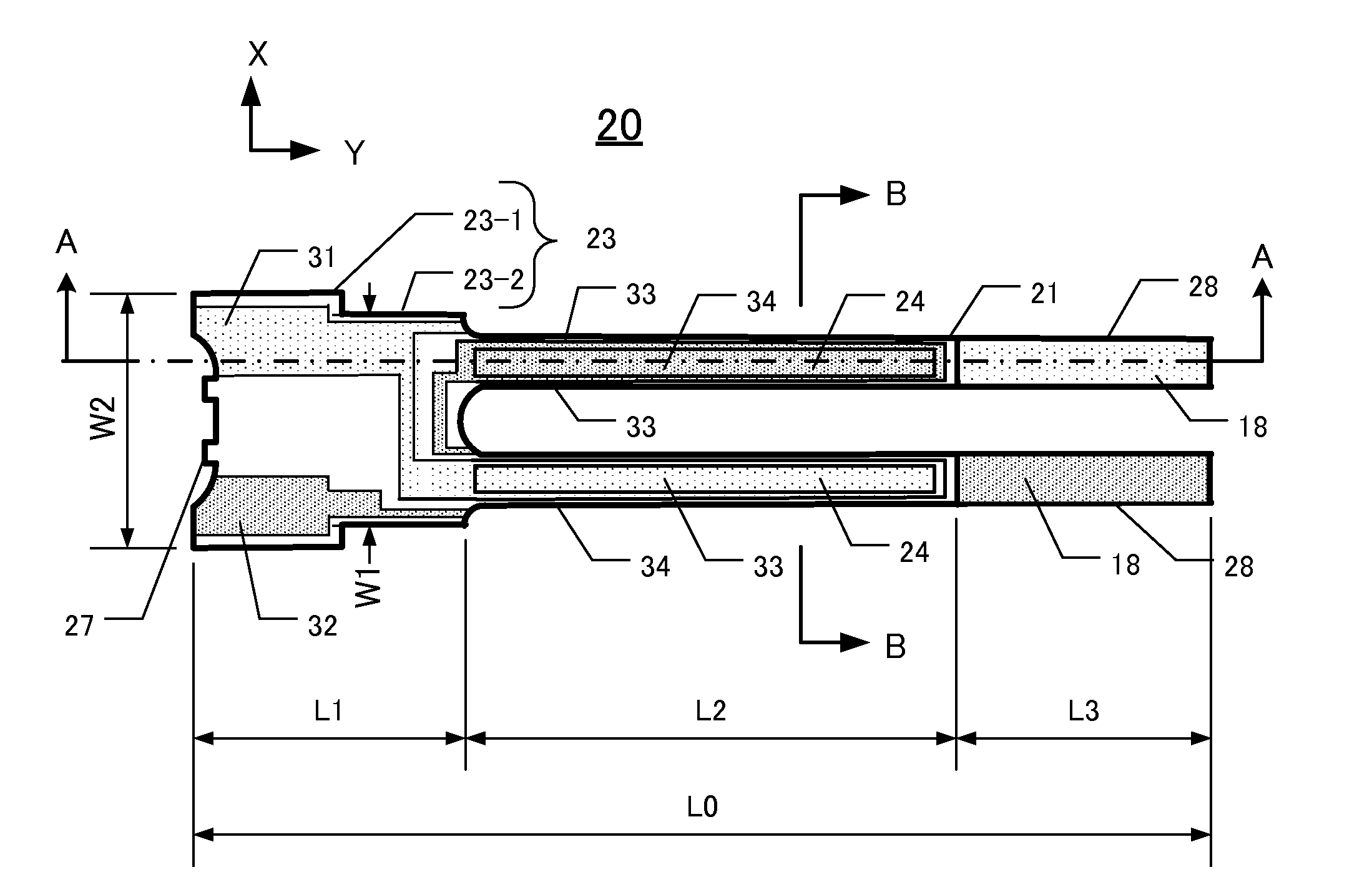
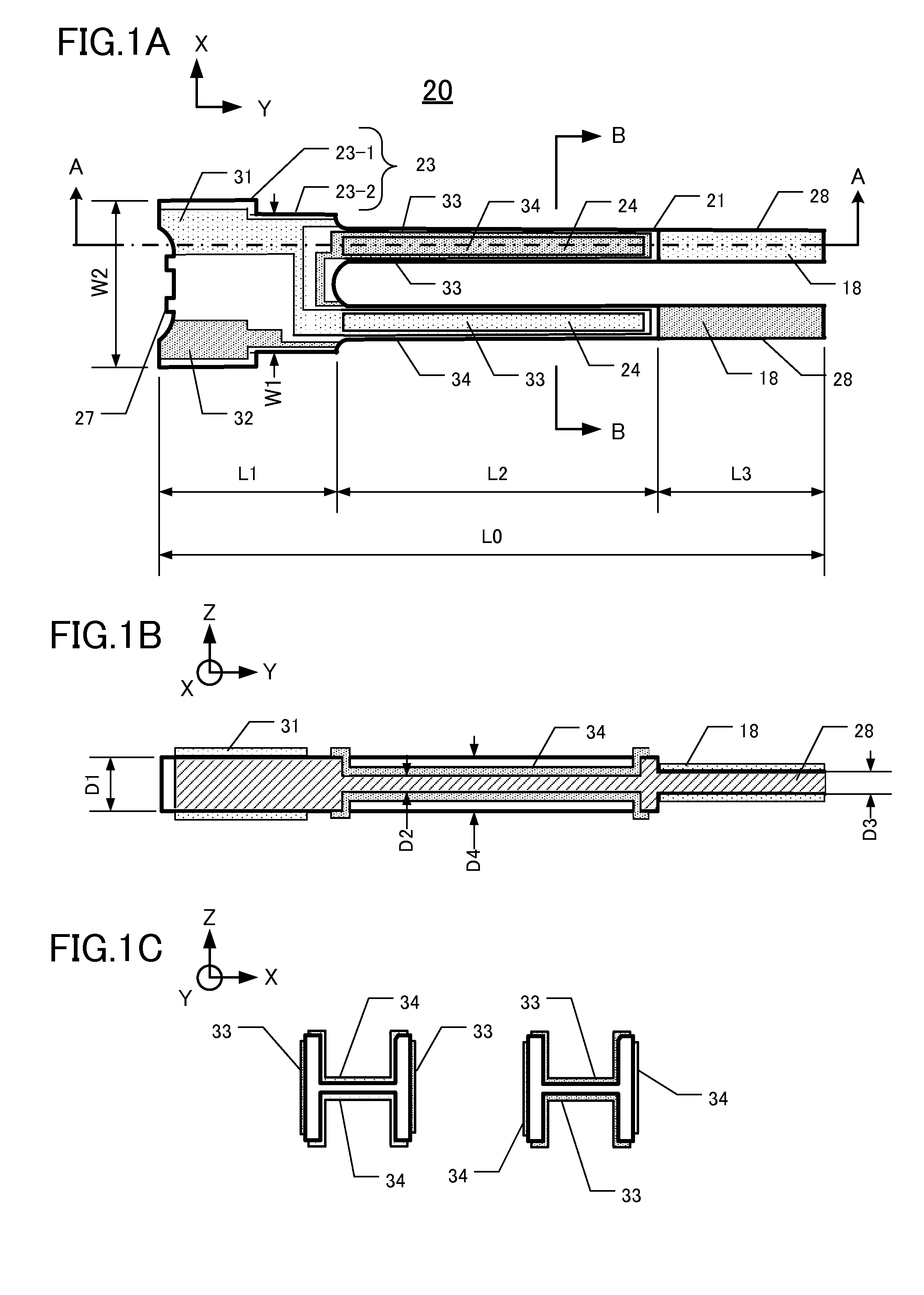
[0051]FIG. 1A is a top view showing whole configuration of the first tuning-fork type crystal vibrating piece 20 of a first embodiment. FIG. 1B is a cross-sectional view taken along line A-A of FIG. 1A. FIG. 1C is a cross-sectional view of a pair of vibrating arms 21 of the first tuning-fork type crystal vibrating piece 20 taken along line B-B of FIG. 1A. The base material of the first tuning-fork crystal vibrating piece 20 is a Z-cut single crystal wafer. As shown in FIG. 1A, the first tuning-fork type crystal vibrating piece 20 is provided with a base portion 23 comprising a first base portion 23-1 and a second base portion 23-2 and a pair of vibrating arms 21 which is bifurcated and extends parallel from the first base portion 23-1 to the right side of FIG. 1A. Tuning portions 28 for frequency adjustment are formed on the distal ends of vibrating arms 21. Connecting portions 27 are formed on the base portion 23 in order to connect the first tuning-fork type crystal vibrating piec...

second embodiment

[0106]FIG. 12A is a top view showing whole configuration of the crystal frame 50. FIG. 12B is a cross-sectional view taken along the E-E line of the FIG. 12A. FIG. 12C is a cross-sectional view taken along the F-F line of the FIG. 12B.

[0107]As shown in FIG. 12A, the crystal frame 50 is comprised of an eighth tuning-fork type crystal vibrating piece 30 having the base portion 23 and the vibrating arms 21, the crystal frame portion 29, the supporting arms 22, and the connecting portions 36. And they are formed integrally as the same thickness. A space 25 is formed between the eighth tuning-fork type crystal vibrating piece 30 and the crystal frame portion 29. The crystal frame 50 is further comprised of a first base electrode 31 and a second base electrode 32 on the crystal frame portion 29, the base portion 23, the supporting arms 22, and the connecting portions 36. The eighth tuning-fork type crystal vibrating piece 30 is very small and oscillates at 32.768 kHz.

[0108]The space 25 de...


PUM

PropertyMeasurementUnit
sizeaaaaaaaaaa
sizeaaaaaaaaaa
sizeaaaaaaaaaa

Abstract

A tuning-fork type piezoelectric vibrating piece (20) is comprised of a base portion (23) comprising a piezoelectric material, a pair of vibrating arms (21) extends parallel from the base portion with a first thickness, a excitation electrode film (33, 34) formed on the vibrating arms, a pair of tuning portions (28) formed at the distal ends of the vibrating arms (21) with a second thickness which is less than the first thickness; and a metal film (18) formed on at least one surface o the tuning portion.

Description

CROSS-REFERENCE TO RELATED APPLICATION[0001]This application claims priority to and the benefit of Japan Patent Application No. 2008-324891, filed on Dec. 22, 2008, in the Japan Patent Office, the disclosure of which is incorporated herein by reference in its entirety.FIELD[0002]The present disclosure relates to tuning-fork type piezoelectric vibrating pieces made of a piezoelectric material and a manufacturing method of piezoelectric device having the piezoelectric vibrating piece.DESCRIPTION OF THE RELATED ART[0003]Various types of clocks, home electric appliances, and consumer electronics, and various types of commercial / industrial electrical apparatus such as information / communication devices and Office-Automation devices utilize at least one oscillator. These oscillators typically are manufactured by packaging a piezoelectric resonator, a piezoelectric vibrating device, or an IC chip as a clock source for addition to and use by an electronic circuit of the apparatus. In other a...

Claims


Application Information

Patent Timeline
Patent Type & Authority Applications(United States)
IPC IPC(8): H01L41/04H01L41/053H01L41/22H01L41/09H01L41/18H01L41/23H01L41/253H01L41/332H03H3/02H03H9/19H03H9/215
CPCH03H3/02H03H9/215Y10T29/42H03H9/19H03H3/04
Inventor ICHIKAWA, RYOICHIIWAI, HIROKIAMANO, YOSHIAKI
Owner NIHON DEMPA KOGYO CO LTD
Why Eureka
Try Eureka