Air Cooling for a Phased Array Radar

a phased array radar and air cooling technology, applied in the field of communication, can solve the problems of high waste heat generation of esa sensors, difficult repair, difficult to solve, etc., and achieve the effects of reducing depth, facilitating air cooling of electronics components, and improving system reliability

Active Publication Date: 2010-06-24
RAYTHEON CO
View PDF12 Cites 46 Cited by
  • Summary
  • Abstract
  • Description
  • Claims
  • Application Information

AI Technical Summary

Benefits of technology

[0005]Certain embodiments may provide numerous technical advantages. For example, technical advantages of certain embodiments may include an integrated structure for a phased array radar that includes thermal interfaces and electrical interfaces located in the same spatial plane, thereby reducing depth. Certain embodiments include integrated, multi-purpose structural elements that facilitate air-cooling of electronics components, thermal management, and structural stiffness

Problems solved by technology

When ESA sensors are used in combat settings, difficulties can arise.
For example, ESA sensors may gene

Method used


Image

  • Air Cooling for a Phased Array Radar
  • Air Cooling for a Phased Array Radar
  • Air Cooling for a Phased Array Radar

Examples


Embodiment Construction

[0016]Embodiments of the disclosure and its advantages are best understood by referring to FIGS. 1 through 7 of the drawings, like numerals being used for like and corresponding parts of the various drawings.

[0017]It should be understood at the outset that although example embodiments of the disclosure are illustrated below, it may be implemented using any number of techniques, whether currently known or not yet in existence. The disclosure should not be limited to the example embodiments, drawings, and techniques illustrated below, including the embodiments and implementation illustrated and described herein. Additionally, the drawings are not drawn to scale.

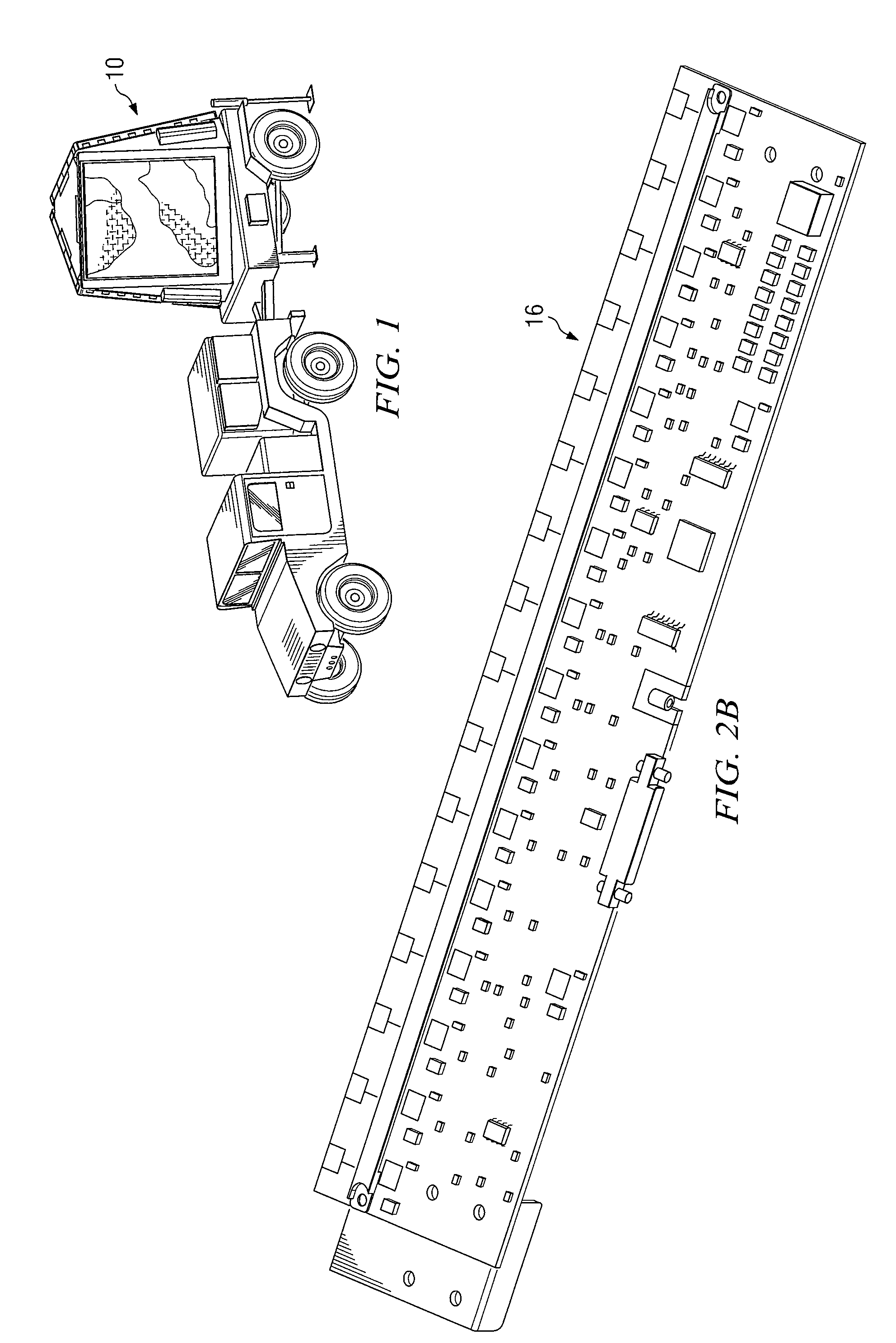
[0018]In combat settings, active electronic scanned array (AESA) sensors may be used to detect the presence of objects. However, difficulties can arise in such settings. For example, AESA sensors may become damaged and need repair, and may be expensive to purchase and maintain. In addition, AESA sensors may be large and heavy, ...


PUM


Abstract

In certain embodiments, a structure for electronic components includes a baseplate having a substantially planar shape. The baseplate defines one or more openings allowing air flow. The structure includes a frame coupled to the baseplate. The frame includes a planar support with a substantially planar shape that is substantially parallel to the baseplate. Then planar support and baseplate at least partially defines one or more plenums. The planar support is also configured to support one or more transmit/receive integrated microwave modules. The frame also includes a plurality of frame supports that define one or more channels for air flow. Each channel corresponds to one of the plenums. Additionally, the frame includes a ventilated panel with a surface defining a plurality of air inlets. The air inlets allow air into one of the one or more plenums. Also, the frame includes one or more thermal interfaces configured to dissipate heat.

Description

TECHNICAL FIELD[0001]The present invention relates generally to communications and, more particularly, to a structure for communications hardware.BACKGROUND[0002]Electronic scanned array (ESA) sensors may be used in a variety of applications. For example, ESA sensors may be used to detect the location of objects. To detect the location of objects, ESA sensors may utilize a plurality of elements that radiate signals with different phases that produce constructive or destructive interference. The phases may be changed to steer the beam to point in a certain direction. ESA sensors may both transmit and receive signals in a particular direction to detect the presence of an object.[0003]When ESA sensors are used in combat settings, difficulties can arise. For example, ESA sensors may generate a high level of waste heat, and may be large, expensive, prone to damage, or difficult to repair.SUMMARY OF THE DISCLOSURE[0004]In certain embodiments, a structure for electronic components includes...

Claims


Application Information

Patent Timeline
IPC IPC(8): H05K7/20
CPCH01Q1/02H05K7/20163H01Q3/26
Inventor MASON, JAMES S.RICHARDSON, RONALD J.WILSON, JAMES S.RAMIREZ, ERIKA
Owner RAYTHEON CO
Why Eureka
Try Eureka