

Heat-transporting device and electronic apparatus
a heat-transporting device and electronic equipment technology, applied in the direction of insulated conductors, instruments, and the details of semiconductor/solid-state devices, can solve the problems of reducing reliability on a strength, complex structure, and disadvantages, and achieve high heat-transporting performan
- Summary
- Abstract
- Description
- Claims
- Application Information
AI Technical Summary
Benefits of technology
Problems solved by technology
Method used
Image

Examples
first embodiment
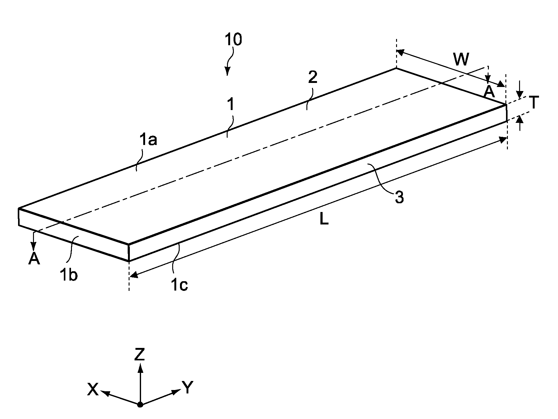
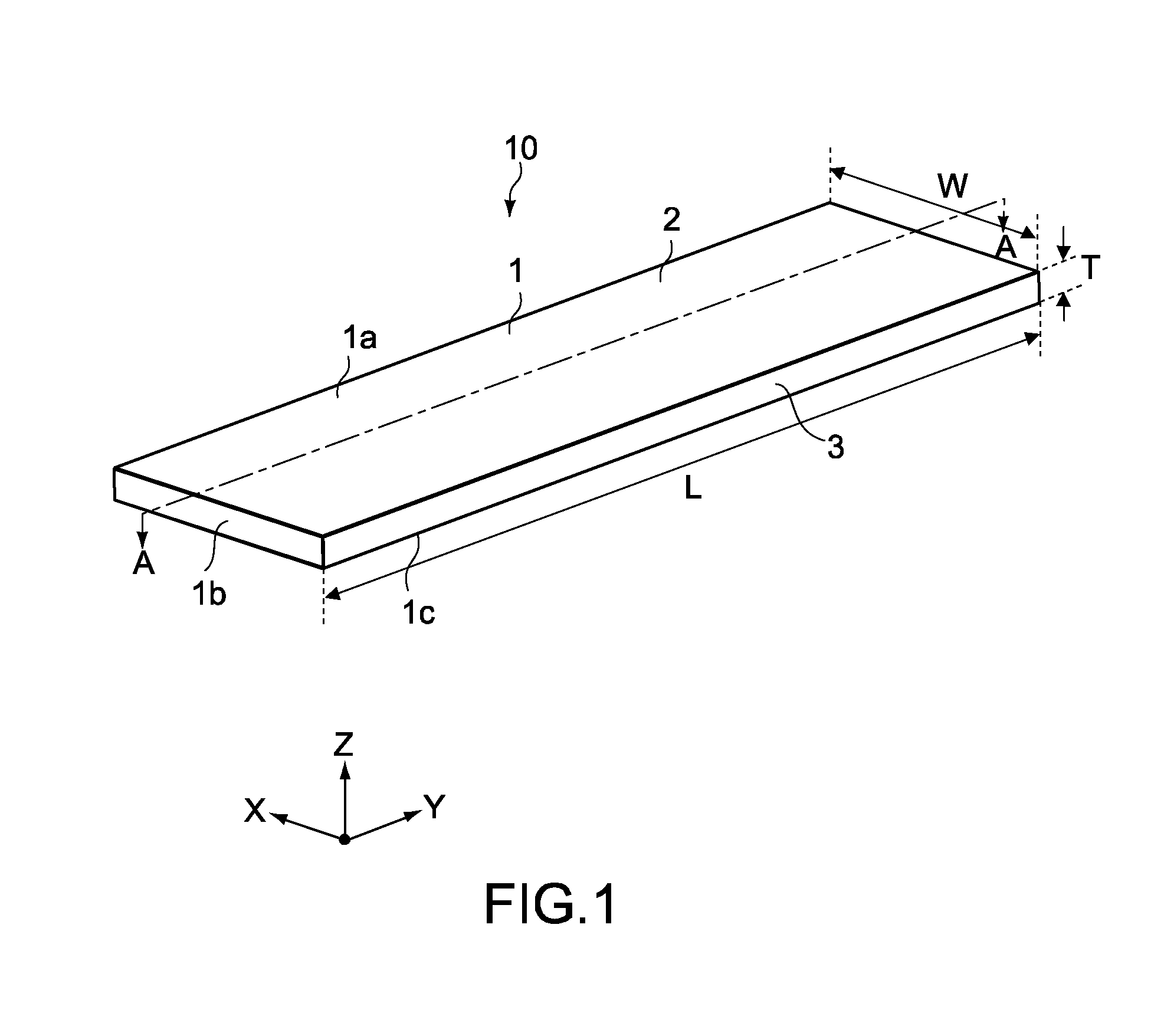
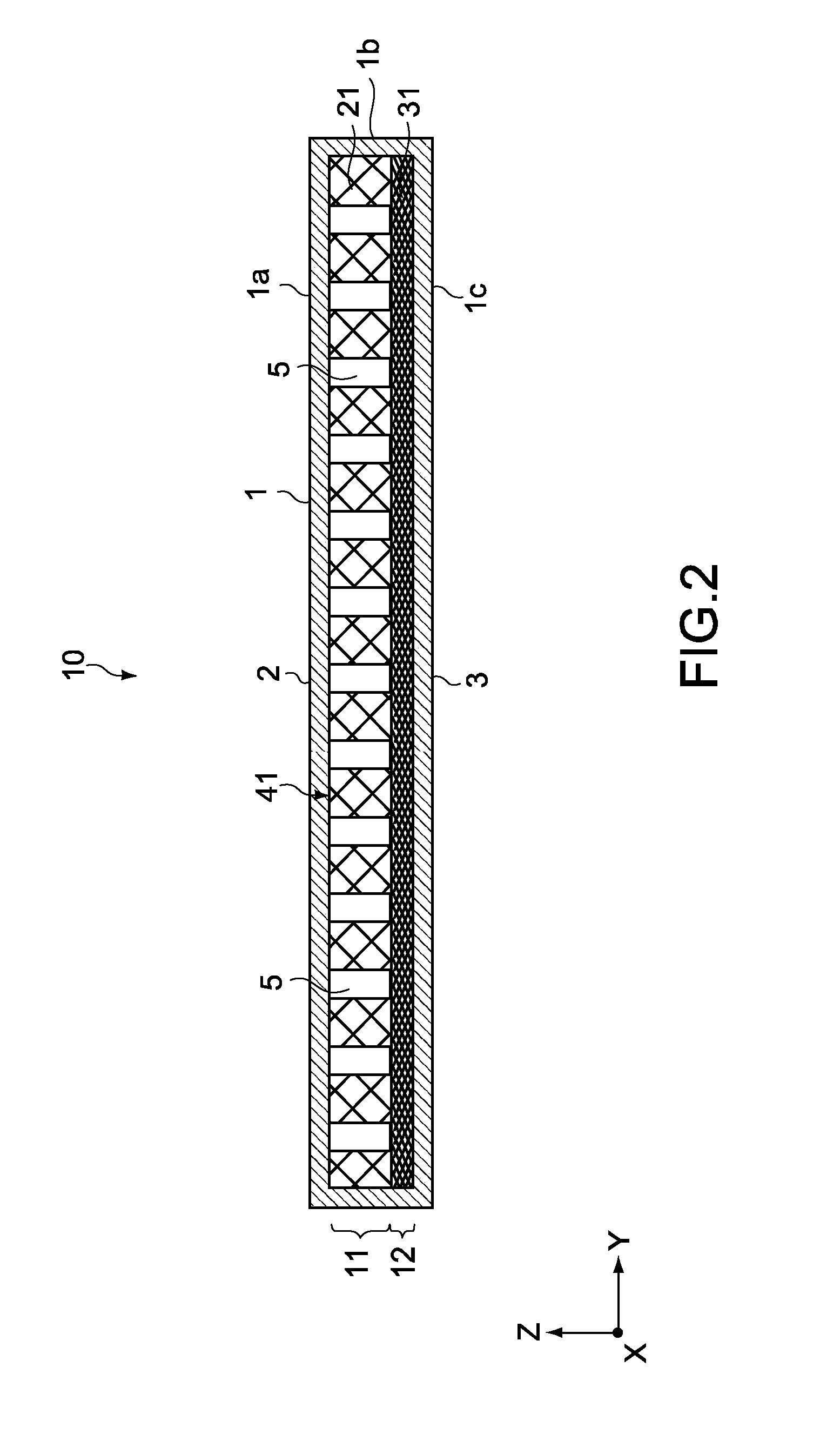
[0086]FIG. 1 is a perspective view of a heat-transporting device according to a first embodiment. FIG. 2 is a cross-sectional side view of the heat-transporting device taken along the line A-A of FIG. 1. It should be noted that in the specification, for brevity of descriptions on the figures, a heat-transporting device, components of the heat-transporting device, and the like may be illustrated in sizes different from actual sizes thereof.
[0087]As shown in the figures, a heat-transporting device 10 includes a thin rectangular plate-like vessel 1 that is elongated in one direction (y-axis direction). The vessel 1 is formed by bonding an upper plate member 2 that constitutes an upper portion 1a of the vessel 1 and a lower plate member 3 that constitutes a circumferential side portion 1b and a lower portion 1c of the vessel 1, for example. A concave portion is formed in the lower plate member 3, and the concave portion forms a space inside the vessel 1.
[0088]Typically, the upper plate ...
second embodiment
[0149]Next, a second embodiment of the present invention will be described.
[0150]The second embodiment is different from the first embodiment in that through-holes 5P provided in a flow-path area P that mainly functions as a flow path are larger than through-holes 5E and 5C provided in the evaporation area E and the condensation area C, respectively. Therefore, that point will mainly be described.
[0151]It should be noted that in descriptions below, components that have the same structures and functions as those of the first embodiment above are denoted by the same symbols, and descriptions thereof will be omitted or simplified.
[0152]FIG. 14 is a cross-sectional side view of a heat-transporting device according to the second embodiment.
[0153]As shown in FIG. 14, a heat-transporting device 50 is in contact with, at one end portion thereof in the longitudinal direction (y-axis direction), the heat source 9 such as a CPU. The heat-transporting device 50 includes the evaporation area E a...
third embodiment
[0168]Next, a third embodiment of the present invention will be described.
[0169]The second embodiment above has been described assuming that the flow-path through-holes 5P are larger than the evaporation through-holes 5E and the condensation through-holes 5C. In the third embodiment, however, the evaporation through-holes 5E and the condensation through-holes 5C are larger than the flow-path through-holes 5P. Thus, that point will mainly be described. It should be noted that in this embodiment, components that have the same structures and functions as those of the second embodiment above are denoted by the same symbols, and descriptions thereof will be omitted or simplified.
[0170]FIG. 16 is a cross-sectional side view of a heat-transporting device according to the third embodiment.
[0171]As shown in FIG. 16, a heat-transporting device 70 includes a laminated body 44 inside the vessel 1. The laminated body 44 includes a vapor-phase mesh member 24 that constitutes the vapor-phase flow ...
PUM
 Abstract
Description
Claims
Application Information