
Cardiovascular power source for automatic implantable cardioverter defibrillators

Inactive Publication Date: 2010-06-24
BOARD OF RGT THE UNIV OF TEXAS SYST
View PDF24 Cites 23 Cited by
  • Summary
  • Abstract
  • Description
  • Claims
  • Application Information

AI Technical Summary

Benefits of technology

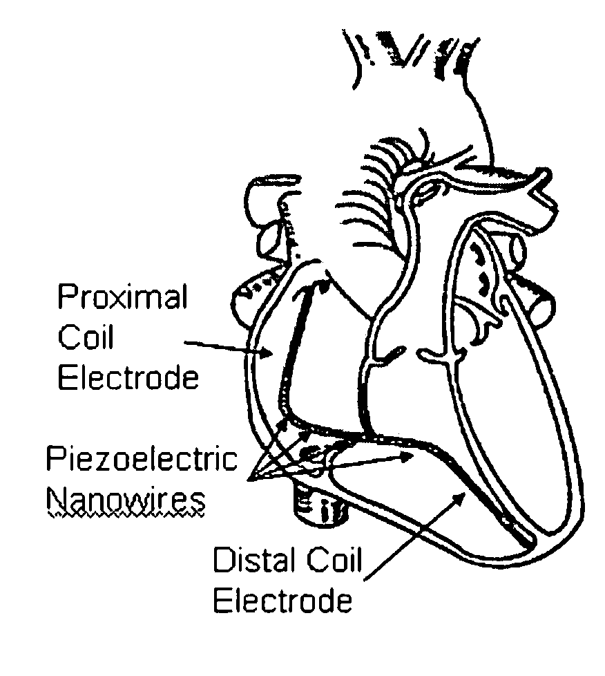
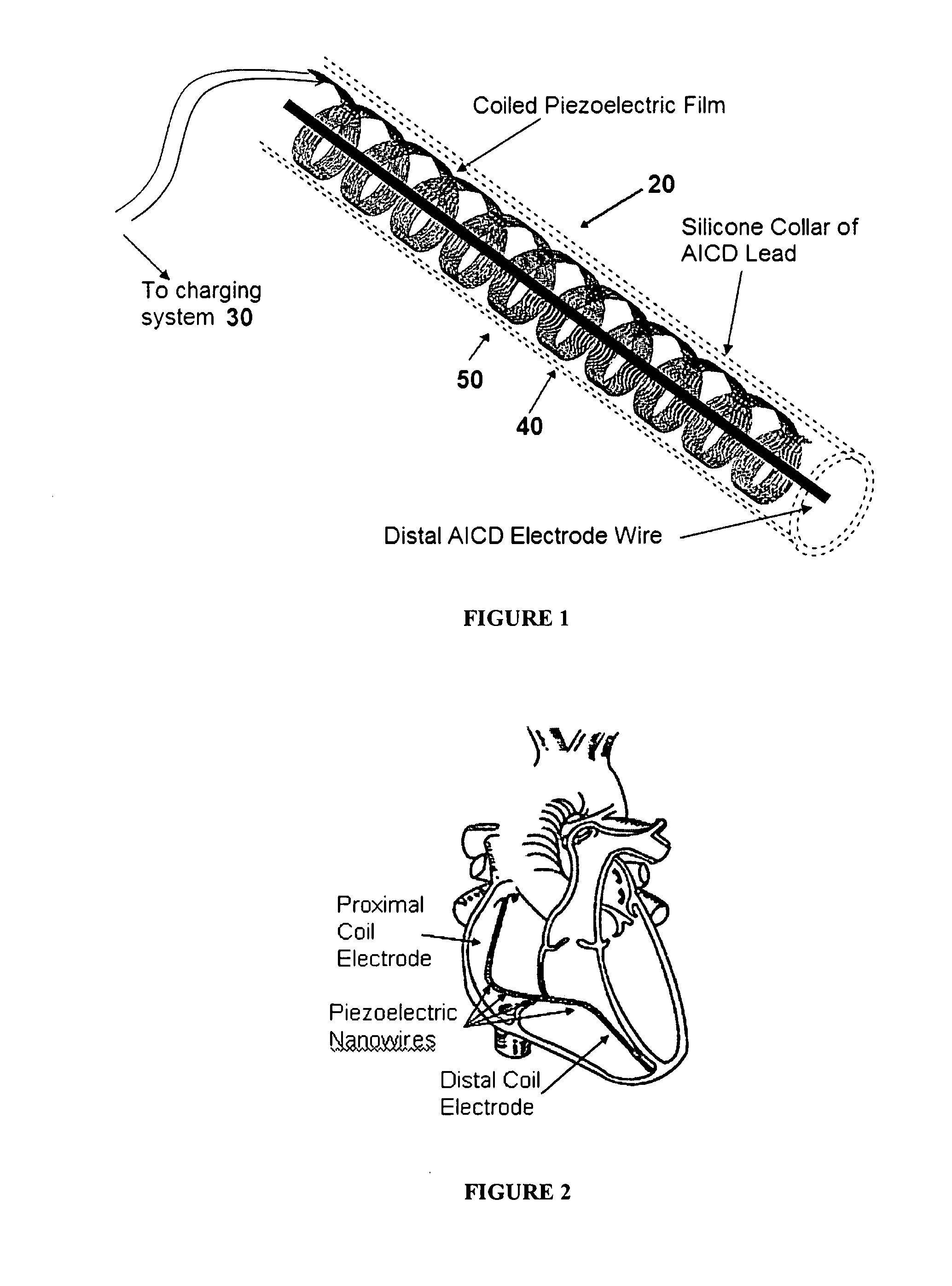
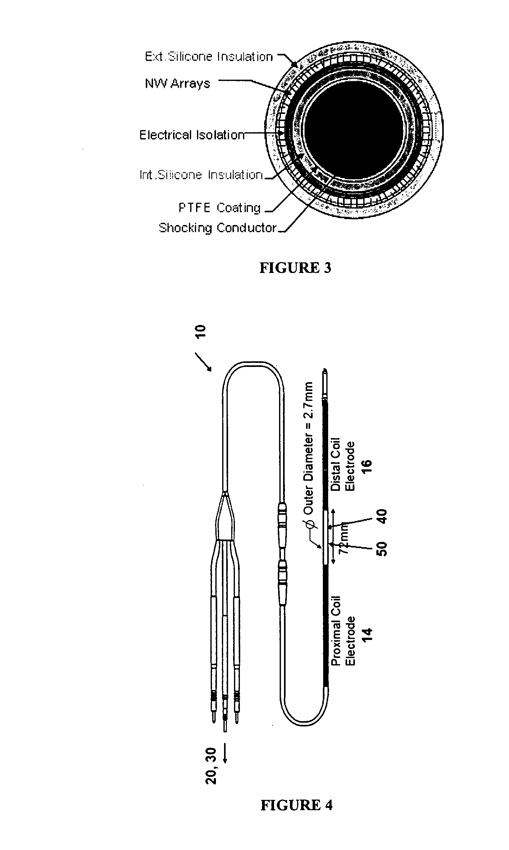
[0016]Accordingly, aspects according to the present invention provide a method and implant suitable for implantation inside a human body that includes a power consuming means responsive to a physiological requirement of the human body, a power source and a power storage device. The power source comprises a sheathed piezoelectric assembly that is configured to generate an electrical current when flexed by the tissue of the body and to communicate the generated current to the power storage device, which is electrically coupled to the power source and to the power consuming means. It is contemplated that the power consuming means can comprise, for example and without limitation, the nominal power requirements of the AICD and / or pacemaker, implantable sensing devices, such as for example, right and left volume and pressure sensors, lung impedance sensors to warn of impending heart failure, and chemical sensors to provide telemetric measures of, for example, glucose, potassium, bun and creatinine. Potential “piggyback” device increase the power demands on the implanted power source.

Problems solved by technology

However, this option also increases the risk of infection and other complications.
While the longevity of the average AICD patient has increased to 10 years after implantation, only 5% of implants functioned for seven years, and this mismatch poses a significant and ever growing clinical and economic burden.
Approximately 90% of AICD failures were caused by normal battery depletion and the shift to dual-chamber models has significantly shortened battery life even further.
Therefore, if the battery is implanted, it must someday be replaced and the battery's limited life is a primary failure mechanism in conventional pacemaker and AICD designs.
Every time a surgery is performed there is an inherent risk and discomfort to the patient.
Even the replacement of the battery is a surgical procedure with inherent risks of its own.
Potential “piggyback” device increase the power demands on the implanted power source.

Method used


Image

  • Cardiovascular power source for automatic implantable cardioverter defibrillators
  • Cardiovascular power source for automatic implantable cardioverter defibrillators
  • Cardiovascular power source for automatic implantable cardioverter defibrillators

Examples


Embodiment Construction

[0038]The present invention may be understood more readily by reference to the following detailed description of the invention and the examples included therein and to the figures and their previous and following description.

[0039]Before the present systems, articles, devices, and / or methods are disclosed and described, it is to be understood that this invention is not limited to specific systems, specific devices, or to particular methodology, as such may, of course, vary. It is also to be understood that the terminology used herein is for the purpose of describing particular embodiments only and is not intended to be limiting.

[0040]The following description of the invention is provided as an enabling teaching of the invention in its best, currently known embodiment. To this end, those skilled in the relevant art will recognize and appreciate that many changes can be made to the various aspects of the invention described herein, while still obtaining the beneficial results of the p...


PUM


Abstract

Aspects according to the present invention provide a method and implant suitable for implantation inside a human body that includes a power consuming means responsive to a physiological requirement of the human body, a power source and a power storage device. The power source comprises a sheathed piezoelectric assembly that is configured to generate an electrical current when flexed by the tissue of the body and communicate the generated current to the power storage device, which is electrically coupled to the power source and to the power consuming means.

Description

FIELD OF THE INVENTION[0001]The present invention generally pertains to a power source whose energy is derived from changes in shape responsive to autonomic movements of the human body. More particularly, to a self-contained power source configured to the implanted in a living organism, such as within a human's heart, such that movement of the heart acting on the power source will cause generation of electrical power.BACKGROUND OF THE INVENTION[0002]Generally, patients with reduced systolic function (LVEF<30%) are now recommended to receive an Automatic Implantable Cardiac Defibrillator (AICD). An AICD is a device that is implanted in the chest to constantly monitor and, if necessary, correct episodes of an abnormal heart rhythm. The primary corrective functions of an AICD are to control tachycardia through cardioversion (low-energy shocks to convert the heart rhythm to a more normal rate) and manage fibrillation through defibrillation. Most AICDs are combined with a Bi-Ventricul...

Claims


Application Information

Patent Timeline
IPC IPC(8): A61N1/36A61B5/02
CPCA61N1/056A61N1/3785H02N2/18H01L41/113B82Y15/00H10N30/30
Inventor FELDMAN, MARC D.CHEN, SHAOCHENHAN, LI-HSINAGUILAR, CARLOS A.AYON, ARTURO A.AGRAWAL, C. MAULIJOHNSON, DAVID M.PATEL, DEVANG N.BAILEY, STEVEN R.KORGEL, BRIAN A.LEE, DOH C.
Owner BOARD OF RGT THE UNIV OF TEXAS SYST
Learn More