High current pulse generator

a pulse generator and high current technology, applied in the direction of electric variable regulation, process and machine control, instruments, etc., can solve the problems of low discharge rate or isolated batteries, and achieve the effect of prolonging the effective operating time of batteries and large impulse torqu

Inactive Publication Date: 2003-11-18
LUXON ENERGY DEVICES CORP
View PDF30 Cites 88 Cited by
  • Summary
  • Abstract
  • Description
  • Claims
  • Application Information

AI Technical Summary

Benefits of technology

FIG. 2 is a schematic diagram illustrating that supercapacitors can discharge to assist battery to meet the power demand at the request of load according to another one preferred embodiment of this invention. FIG. 2 is based on the second embodiment of the present invention for generating high current pulse to meet an increasing power demand of loads, such as, the motor of power drills, the engine of motorcycles and automobiles, as well as the actuator of automatic systems. Similar to FIG. 1, the high current pulses generator 20 also comprises battery B as a voltage source, supercapacitors C1 and C2 as an energy storage unit, and a SPDT, 3-port electromagnetic relay for switching the supercapacitors to discharge position. However, a solenoid S is included in the generator of FIG. 2, and battery B supplies a DC current that is within the normal discharge rates of battery for charging the supercapacitors, as well as for driving the motor M that requires low power for initial operation. During charging phase, with the relay at normally closed (S1a-S1, S2a-S2 and S3a-S3) state the supercapacitors C1 and C2 are connected in parallel, and the DC current flowing through S is below the turn-on threshold of the device. As the power demand of M increases, for example, at the moment when the drill bit of a power drill is penetrating a work piece or at the ignition of engines of vehicles, the motors require a large impulse torque demanding more current output from battery B. Along with an increasing DC current flowing through S and exceeding the turn-on threshold of S, the switch of S is closed and the electromagnetic relay is switched from normally closed to normally open (S1-S1b, S2-S2b and S3-S3b). In a real-time response, the supercapacitors C1 and C2 are connected in series and discharge to generate a high current pulse to M in order to meet the power demand. In the foregoing operation, the discharge of battery B is kept at low rates. Thus, no abrupt voltage drop will occur and the effective operating time of battery is prolonged.

Problems solved by technology

When the loads demand large currents, the supercapacitors will promptly supply the required power, leaving batteries isolated or under a condition of low discharge rate.

Method used


Image

  • High current pulse generator
  • High current pulse generator
  • High current pulse generator

Examples


example 2

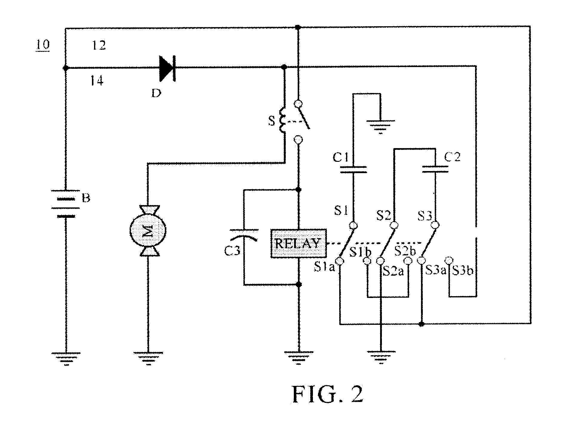
Using 6 pieces of 3.6V.times.1600 mAh lithium ion batteries, which are first grouped in 3 sets of double batteries connected in-series, and then the 3 sets are connected in-parallel to form a battery pack of 7.2V.times.4800 mAh, together with 2 pieces of 6.5V.times.40F supercapacitors with ESR of 30 m .OMEGA., a high current pulses generator as depicted by FIG. 2 is constructed. The generator is capable of igniting a 2000-ml combustion engine of a 6-cylinder automobile. Also the generator weighed 1.4 lbs. is measured to deliver an electric power of 720 W (12V.times.60A) for 2 seconds per one full charge of supercapacitors. From the foregoing two examples, the present invention demonstrated the following features:

1. Primary batteries such as alkaline batteries can be used to operate electric power tools.

2. With the assistance of supercapacitors, rechargeable batteries of low power density such as NiMH and lithium ion can be used to replace batteries of high power density such as lead...


PUM

PropertyMeasurementUnit
currentaaaaaaaaaa
electric poweraaaaaaaaaa
chargesaaaaaaaaaa

Abstract

The present invention provides a high current pulse generator for DC powered devices. The generator includes batteries as the power source that charges supercapacitors as well as provides power to the loads as required. During charging, the supercapacitors are connected in parallel, but they are switched to series connection by relays at the moment that the loads demand large currents. No other controlling means except for relays in the circuit is employed, so that the electric arrangement is simple, reliable, and cost-effective. As the batteries are designed to deliver currents at low discharge rates, the effective use-time of batteries is prolonged. Furthermore, due to the high power densities of supercapacitors, the readily available alkaline batteries can be utilized in the power unit for electric power tools.

Description

BACKGROUND OF INVENTION1. Field of InventionThe present invention relates to a compact power module for generating impulses of high current for driving electric motors to create impulse torque in short duration, thereby energizing hand-held tools, igniting combustion engines, or actuating automatic systems. More specifically, the present invention relates to a switching capacitor without moving parts wherein supercapacitors, ultracapacitors, or electric double layer capacitors are configured from parallel connection during charging phase to series connection at the time of use by electromagnetic switching elements to discharge for generating the desired impulses.2. Description of Related ArtImpulse energy is very useful in numerous industries. For example, it can be used for crushing stones (U.S. Pat. No. 6,058,029), for vaporizing metal (U.S. Pat. No. 5,359,279), for removing pollutant particles (U.S. Pat. No. 4,162,417), and for collecting blood sample (U.S. Pat. No. 5,839,446).Ma...

Claims


Application Information

Patent Timeline
Patent Type & Authority Patents(United States)
IPC IPC(8): H02J7/34H02J7/00H02M9/04
CPCB25B21/00H02J7/345H02J7/0024
Inventor SHIUE, LIH-RENSUN, ABELCHUNG, HSING-CHEN
Owner LUXON ENERGY DEVICES CORP
Why Eureka
Try Eureka