Environmental Model Maintenance Using Event-Based Vision Sensors

a technology of event-based vision and environmental model, applied in the field of environmental model maintenance using event-based vision sensors, can solve the problems of high power consumption of most depth sensors, high computational cost, and high power consumption of passive depth sensing approaches such as stereo cameras or depth inference from priors, so as to reduce the amount of data, reduce power consumption, and reduce power consumption

Pending Publication Date: 2022-02-24
SONY ADVANCED VISUAL SENSING AG
View PDF0 Cites 0 Cited by
  • Summary
  • Abstract
  • Description
  • Claims
  • Application Information

AI Technical Summary

Benefits of technology

[0006]On the other hand, event-based vision sensors offer many advantages, mainly by intrinsically compressing the data stream, thus reducing the amount of data that a processing unit needs to process. They also use less power than conventional illumination sensors (cameras). Furthermore, the event-based vision sensor pixels continuously sense the visual changes in the scene at a high frequency (up to multiple kilohertz(kHz)) and report them with a very low latency. This makes the event-based vision sensor an ideal sensor for always-on tasks such as monitoring the device's environment, smart sensor control or data enhancement of secondary sensing modalities.
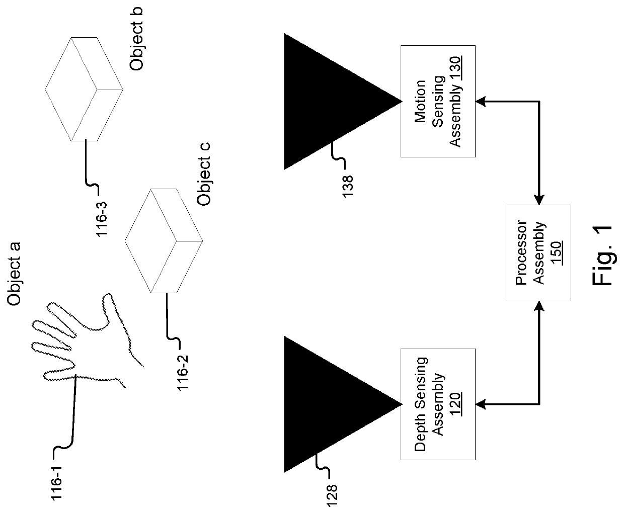
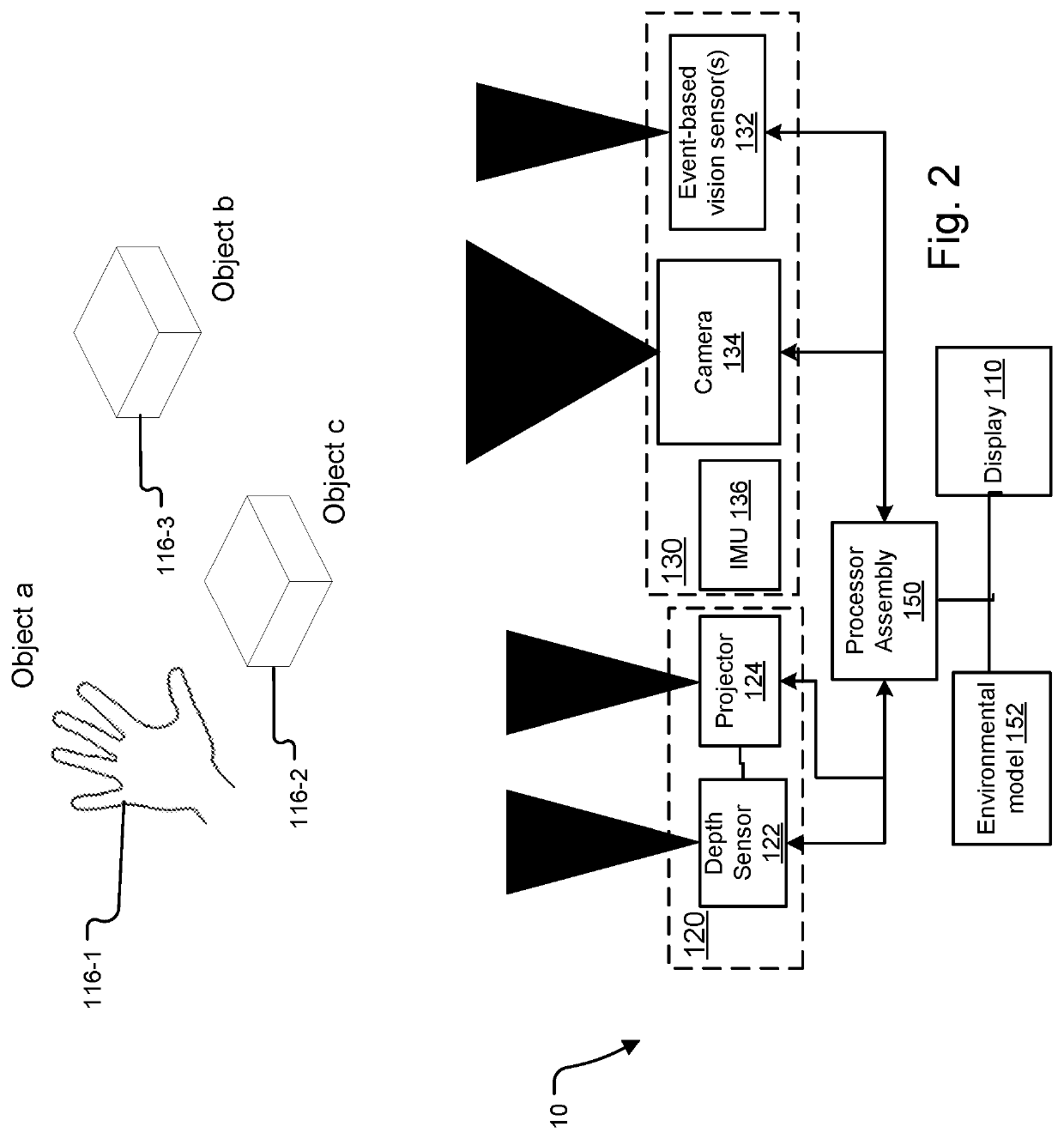
[0007]The present approach leverages advantages of event-based sensors to reduce the power consumption. Conventional motion sensing assemblies may typically be composed of conventional machine vision cameras which may be used to infer information from incident light and one or several inertial measurement units (IMU) which may be used to infer information about accelerations and rotational velocities as well as the bearing of the device. From the incident light, both information about the devices' own motion and about motion and changes in the devices' surroundings which may be caused by moving objects or changes in illumination may be inferred. From the IMU measurements only an inference on the devices' own motion is possible. If a device is placed in a non-static environment changes in the surroundings may not be sensed by an IMU and either the illumination will need to be measured or depth measurements must be triggered. In order to react quickly to such changes, the surroundings must be continuously measured in intervals directly relating to the minimally admitted delays in the application for which depth measurements or inferred data are used and still delays may not be avoided. Such requirements and delays may make it impossible to reach the optimal control scheme for the involved sensors, e.g. minimal number of depth measurements theoretically necessary for any given application, which would result in the lowest power consumption. Image captures, which are unnecessary, will increase power demand and limit the achievable gain in power demand further. Adding an event-based sensing cycle solves these issues. Conventional illumination sensors (cameras) need more power than event-based sensors and have a much lower sampling frequency (typically a few tens of Hz compared to multiple kHz). Illumination measurement (image) captures take longer and are more delayed compared to measurements with an event-based sensor. Including event-based sensors enables the detection of changes in the environment very quickly and hence allows depth measurement trigger times derivation, areas or other control parameters much closer to the theoretical optimum while needing less power than conventional motion sensing assemblies. Additionally, the high temporal resolution of event-based vision sensors allows a more accurate estimation of the dynamic state of objects and hence a more accurate prediction of their state at future points in time.

Problems solved by technology

Operating depth sensors can be expensive for these computing devices in a number of ways.
Most depth sensors consume high levels of power.
Passive depth sensing approaches such as stereo cameras or depth inference from priors, for example using neural networks (e.g. convolutional), are computationally expensive, and thus power intensive.
Additionally, operating the depth sensors is also computationally expensive.
Operating conventional image sensors (cameras) is also expensive for these computing devices.
While consuming lower levels of power compared to depth sensors, their power consumption is still considerable, especially when operating at high frequencies and / or resolutions.
Additionally, their operation produces high amounts of data that must be stored, moved and processed, resulting in a high demand of both power and memory.
In order to react quickly to such changes, the surroundings must be continuously measured in intervals directly relating to the minimally admitted delays in the application for which depth measurements or inferred data are used and still delays may not be avoided.
Such requirements and delays may make it impossible to reach the optimal control scheme for the involved sensors, e.g. minimal number of depth measurements theoretically necessary for any given application, which would result in the lowest power consumption.
Image captures, which are unnecessary, will increase power demand and limit the achievable gain in power demand further.
Illumination measurement (image) captures take longer and are more delayed compared to measurements with an event-based sensor.

Method used


Image

  • Environmental Model Maintenance Using Event-Based Vision Sensors
  • Environmental Model Maintenance Using Event-Based Vision Sensors
  • Environmental Model Maintenance Using Event-Based Vision Sensors

Examples


Embodiment Construction

[0030]The invention now will be described more fully hereinafter with reference to the accompanying drawings, in which illustrative embodiments of the invention are shown. This invention may, however, be embodied in many different forms and should not be construed as limited to the embodiments set forth herein; rather, these embodiments are provided so that this disclosure will be thorough and complete, and will fully convey the scope of the invention to those skilled in the art.

[0031]As used herein, the term “and / or” includes any and all combinations of one or more of the associated listed items. Further, the singular forms and the articles “a”, “an” and “the” are intended to include the plural forms as well, unless expressly stated otherwise. It will be further understood that the terms: includes, comprises, including and / or comprising, when used in this specification, specify the presence of stated features, integers, steps, operations, elements, and / or components, but do not pre...


PUM


Abstract

A method and system comprising one or more event-based vision sensors for monitoring an environment and one or more depth sensors monitoring the environment as well as potentially additional sensors to monitor the environment such as inertial measurement units and image sensors. The device as a processor assembly will then monitor the event-based vision sensor and the depth sensor and other sensors and determine whether to adapt a control schem, such as activate, the depth sensor to acquire depth information of the environment based on the response of the event-based vision sensor. This approach leverages advantages of event-based sensors to reduce the power consumption but still react quickly to such changes by continuously measuring intervals directly relating to the minimally admitted delays in the application for which depth measurements or inferred data are used.

Description

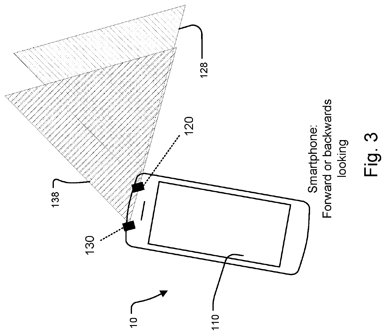
RELATED APPLICATIONS[0001]This application claims the benefit under 35 USC 119(e) of U.S. Provisional Application No. 62 / 796,742, filed on Jan. 25, 2019, which is incorporated herein by reference in its entirety.BACKGROUND OF THE INVENTION[0002]Depth sensors and machine vision and cameras (such as CMOS image sensors) are common components of many computing devices. Especially, mobile computing devices, such as smartphones and tablet devices, use one or a combination of the two sensing types for facial recognition and gesture tracking. The depth sensors are also helpful to track the environment more generally so the device can know when the user approaches or what the distance to objects is, while cameras allow an estimation of the reflectance and / or luminous emittance properties of these objects. In addition, a SLAM (Simultaneous localization and mapping) method is often used to estimate the position of the apparatus in space. The SLAM method estimates the apparatus pose (position a...

Claims


Application Information

Patent Timeline
Patent Type & Authority Applications(United States)
IPC IPC(8): H04N5/232G06F3/0346G06F11/30G06F1/3206
CPCH04N5/23241G06F1/3206G06F11/3058G06F3/0346G06F3/011G06F1/163G06F1/1626G06F1/1686G06F1/1684G06F3/0304G06F3/017G06F1/3231G06F1/3215G06F1/3287G06F1/1694Y02D10/00H04N23/65
Inventor BRÄNDLI, CHRISTIANLEWIS, JAMES G.ISLER, STEFAN
Owner SONY ADVANCED VISUAL SENSING AG
Why Eureka
Try Eureka