
Wireless dynamic power control of an implantable sensing device and methods therefor

a sensing device and wireless technology, applied in electrotherapy, therapy, etc., can solve the problems of distorted physiological parameters such as temperature and pressure, inability to easily be used for deeply implanted devices, and inability to easily achieve deep implanted devices, etc., to achieve enhanced functionality and data rate transfer

Inactive Publication Date: 2010-06-24
INTEGRATED SENSING SYST INC
View PDF10 Cites 137 Cited by
  • Summary
  • Abstract
  • Description
  • Claims
  • Application Information

AI Technical Summary

Benefits of technology

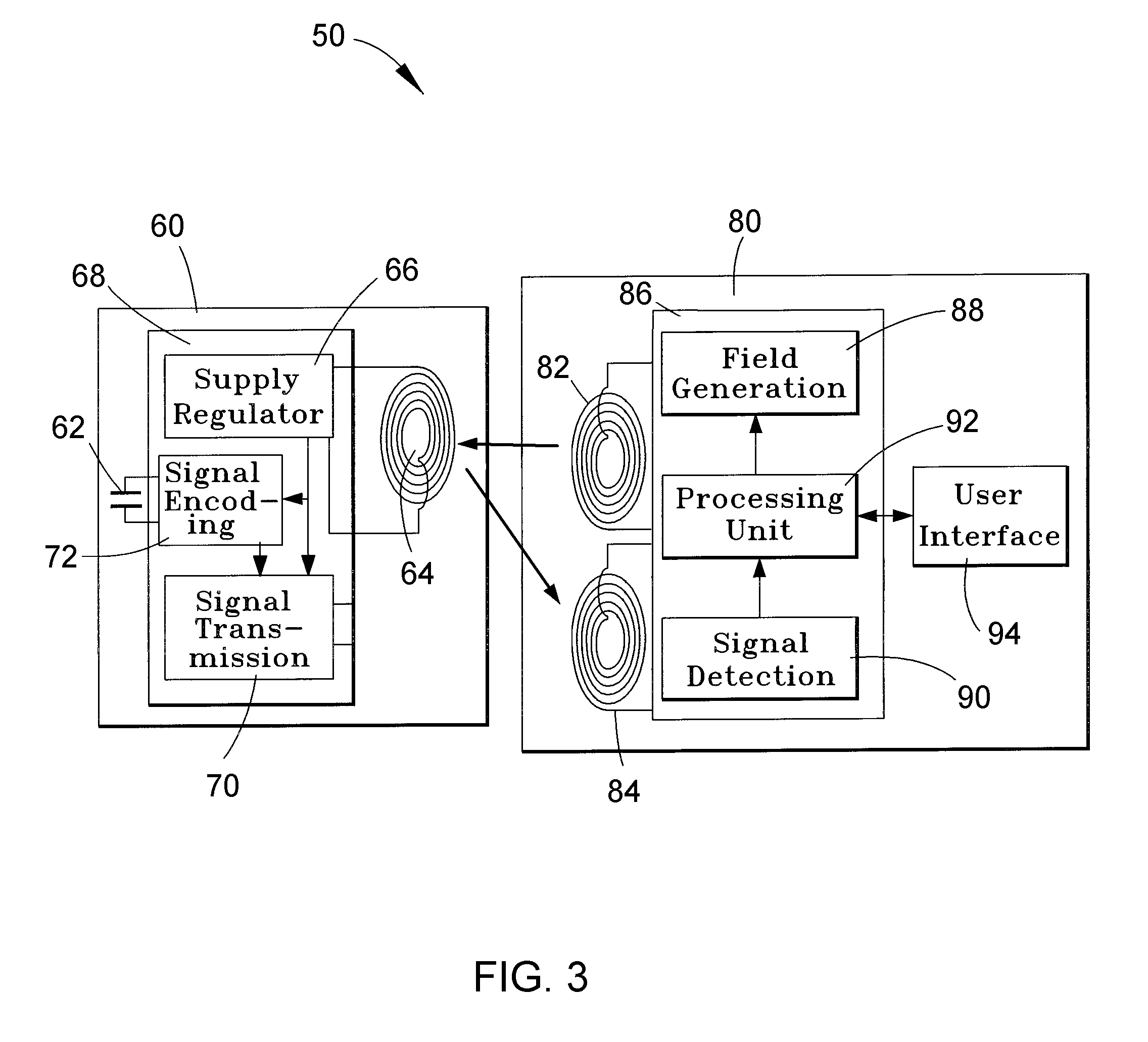
[0008]The present invention provides communication systems and methods for dynamically controlling the power wirelessly delivered by a remote reader unit to a separate sensing device, such as a device adapted to monitor a physiological parameter within a living body, including but not limited to intraocular pressure, intracranial pressure (ICP), and cardiovascular pressures that can be measured to assist in diagnosing and monitoring various diseases. According to a particular aspect of the invention, such a communication system can be adapted to provide enhanced functionality and data rate transfers by combining digital and analog communication between the sensing device and reader unit.
[0009]The communication system includes at least one telemetry antenna within the reader unit and adapted for electromagnetically delivering power to the sensing device, at least one sensing element within the sensing device for sensing a parameter of the fluid and producing an output based on the parameter, electronic components within the sensing device for processing the output of the sensing element and generating therefrom a processed data signal of the sensing device, and at least one telemetry antenna within the sensing device for receiving the power electromagnetically delivered by the reader unit and communicating the processed data signal to the reader unit. The electronic components are adapted to be powered at an operating power level. The communication further includes means for preventing the power supplied to the electronic components from exceeding the operating power level.
[0010]The communication method generally entails a reader unit and sensing device that can be of the type described above, and involves electromagnetically delivering power from a telemetry antenna within the reader unit to a telemetry antenna within the sensing device, and preventing the power supplied to electronic components of the sensing device from exceeding the operating power level.
[0011]The communication scheme and method are particularly intended for use with wireless implantable medical devices that obtain all of their power from a reader unit located outside the body, enabling safe, detailed, real-time, and continuous monitoring of a physiological parameter. According to a preferred aspect of the invention, excess power supplied to the device can be avoided, thereby eliminating the requirement to dissipate heat, avoiding potential measurement errors arising from localized heating or temperature gradients within the device, and avoiding unnecessary heating of tissue that surrounds the device when implanted in a body.

Problems solved by technology

The higher frequencies (greater than 100 MHz) suffer from tissue absorption and cannot easily be used for deeply implanted devices.
However, physiological parameters such as temperature and pressure can be distorted by excessive power delivered to a tele-powered implant.
Though systematic errors attributable to constant temperature gradients or peculiar transfer characteristics can be overcome by calibration, attempts to regulate and dissipate excess absorbed power within an implant will often result in localized heating and temperature gradients within the implant, including the temperature sensor, contributing to erroneous temperature measurements and, therefore, erroneous pressure measurements.
As such, varying power dissipation levels within an implant can cause uncertainty due to the effects on the operation of the temperature sensor.
Excess power dissipation can also be detrimental to the transducer parameter extraction circuit used in implants.
), even a small amount of excess power cannot be tolerated in the implant, necessitating some type of management scheme.

Method used


Image

  • Wireless dynamic power control of an implantable sensing device and methods therefor
  • Wireless dynamic power control of an implantable sensing device and methods therefor
  • Wireless dynamic power control of an implantable sensing device and methods therefor

Examples


Embodiment Construction

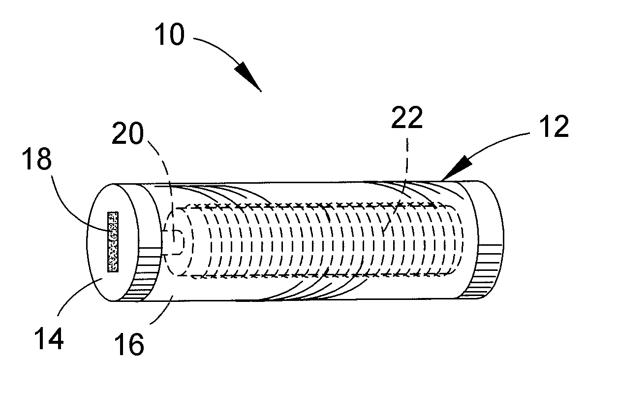
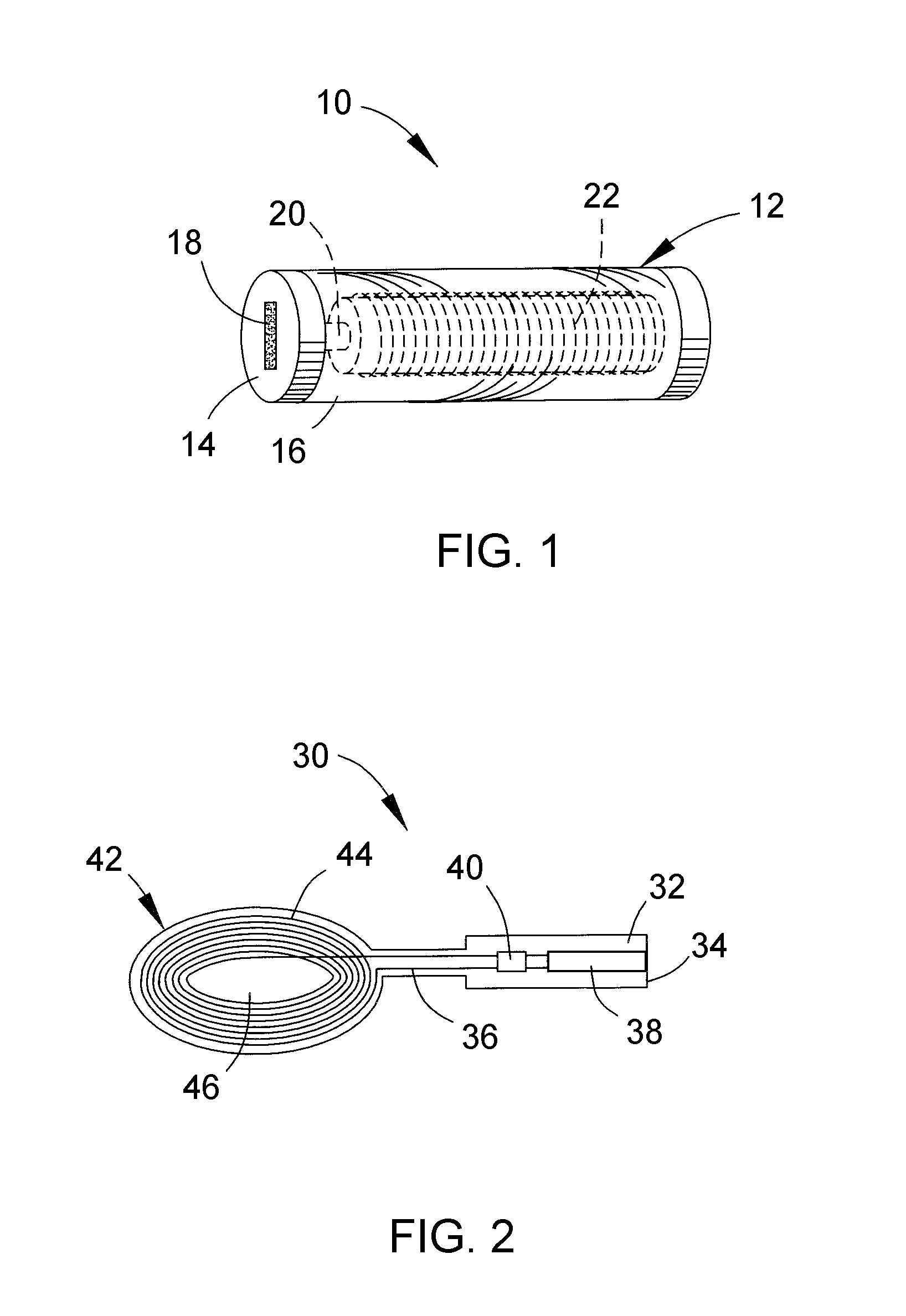
[0019]FIG. 1 schematically depicts one example of an implantable sensing device 10 of a type that can be used with the present invention. The device 10 is represented as having a cylindrical housing 12, which is convenient for placing the sensing device 10 within certain types of anchors adapted to secure the sensing device 10 to or within a wall-like structure, for example, the skull or the atrial or ventricular septum of the heart. Other exterior shapes for the housing 12 are also possible to the extent that the exterior shape permits placement of the sensing device 10 in a desired location or assembly of the sensing device 10 with an anchor. The cylindrical-shaped housing 12 of FIG. 1 includes a flat distal face 14, though other shapes are also possible, for example, a torpedo-shape in which the peripheral face 16 of the housing 12 immediately adjacent the distal face 14 is tapered or conical (not shown). The housing 12 can be formed of glass, for example, a borosilicate glass su...


PUM


Abstract

Communication systems and methods for dynamically controlling the power wirelessly delivered by a remote reader unit to separate sensing device, such as a device adapted to monitor a physiological parameter within a living body, including but not limited to intraocular pressure, intracranial pressure (ICP), and cardiovascular pressures that can be measured to assist in diagnosing and monitoring various diseases. The communication method entails electromagnetically delivering power from at least one telemetry antenna within the reader unit to at least one telemetry antenna within the sensing device, and controlling the power supplied to the sensing device within a predetermined operating power level range of the sensing device.

Description

CROSS REFERENCE TO RELATED APPLICATIONS[0001]This application claims the benefit of U.S. Provisional Application Nos. 61 / 203,400 and 61 / 203,401, both filed Dec. 22, 2008, and U.S. Provisional Application No. 61 / 268,731 filed Jun. 17, 2009. The contents of these prior patent applications are incorporated herein by reference.BACKGROUND OF THE INVENTION[0002]The present invention generally relates to implantable medical devices and to communication schemes and medical procedures performed therewith. More particularly, this invention relates to systems and methods for dynamically controlling power wirelessly delivered to such devices.[0003]Wireless devices such as pressure sensors have been implanted and used to monitor various physiological parameters of humans and animals, including but not limited to heart, brain, bladder and ocular function. With this technology, capacitive pressure sensors are often used, by which changes in pressure cause a corresponding change in the capacitance ...

Claims


Application Information

Patent Timeline
IPC IPC(8): A61N1/08
CPCA61N1/3787
Inventor NAJAFI, NADERBRAUCHLER, FREDCRUZ, VINCENT
Owner INTEGRATED SENSING SYST INC
Learn More