Light Focusing in Linear Channel Arrays

a linear channel array and light focusing technology, applied in the direction of instruments, material analysis through optical means, optical elements, etc., can solve the problem of non-uniform illumination of the capillary channel

Inactive Publication Date: 2010-07-01
THE RES FOUND OF STATE UNIV OF NEW YORK
View PDF5 Cites 5 Cited by
  • Summary
  • Abstract
  • Description
  • Claims
  • Application Information

AI Technical Summary

Benefits of technology

[0005]In some embodiments the invention relates to a linear multi-capillary array formed of active or working capillaries and, interposed therebetween, composite optical insertions. The array may be surrounded (or partially surrounded) by a transparent medium. The refractive index of at least one of the media that comprise the working capillaries is different from the refractive index of at least one of the media that comprise the composite optical insertions. In further embodiments, the refractive indices of said active capillaries, said composite insertions, and the medium surrounding the array in the region of the system's light-path or detection zone are selected so that they provide maximum (or at least improved) transmission of the laser beam through the linear multi-capillary array. In further embodiments, the refractive indices of the linear multi-capillary array capillaries, the outer layer of each of the composite insertions, and the surrounding media are such that they form an optically homogeneous system, and the refractive index and the shape of the inner regions bounded by the outer layer of the composite insertions are such that they enable a guiding of the illumination beam through the linear multi-capillary array with maximum transmittance coefficient.
[0012]In other embodiments, the invention relates to a linear multi-capillary array comprising: a plurality of active capillaries and, preferably commingled therewith, preferably in one-to-one alternating relation, a plurality of composite optical insertions; wherein said plurality'of active capillaries and said composite optical insertions comprise at least two media with different refractive indices, wherein the refractive indices of said active capillaries, said composite insertions and a medium surrounding the linear multi-capillary array's detection zone are selected so that they provide maximum (or at least improved) transmission of the laser beam through the linear multi-capillary array.

Problems solved by technology

However, reflection and refraction of the laser beam at the walls of individual capillaries causes nonuniform illumination of the capillary channels.

Method used


Image

  • Light Focusing in Linear Channel Arrays
  • Light Focusing in Linear Channel Arrays
  • Light Focusing in Linear Channel Arrays

Examples


example 1

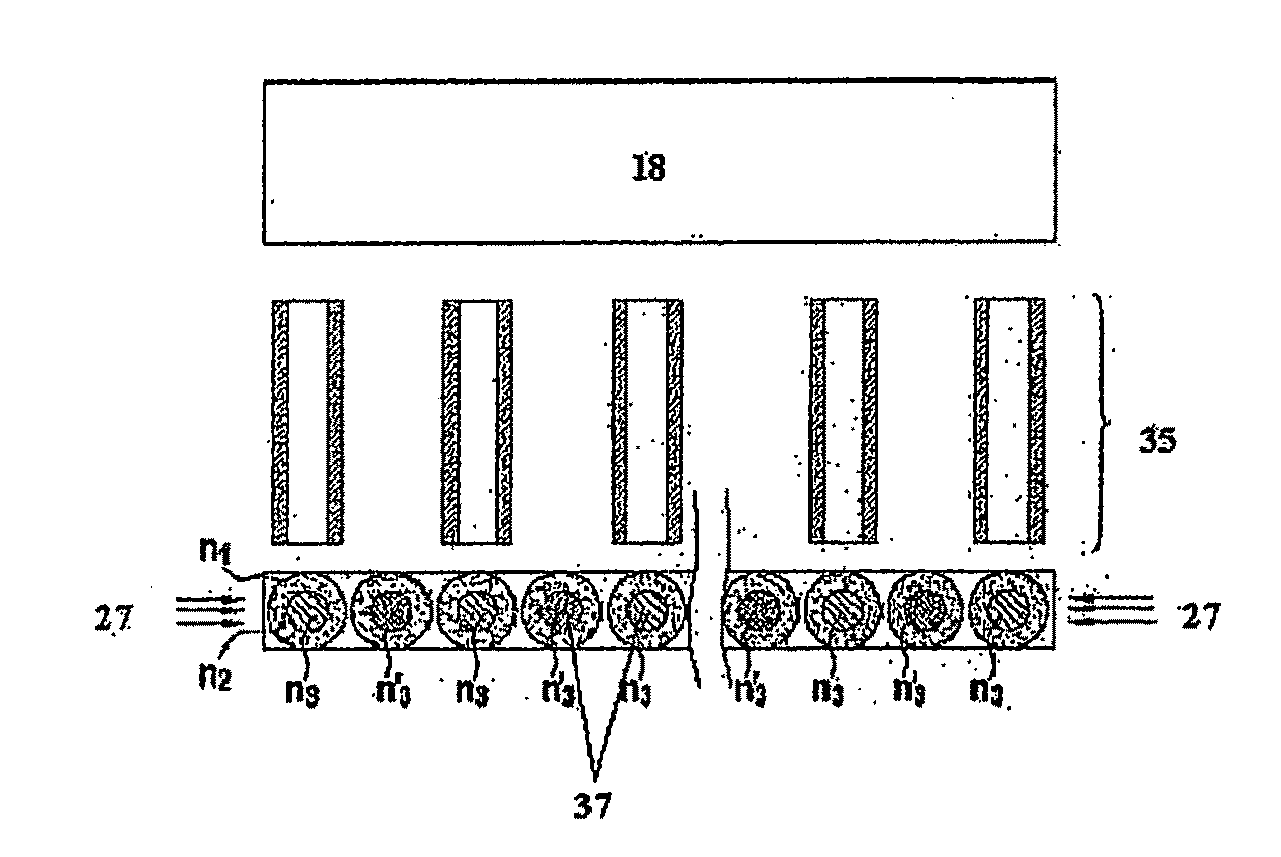
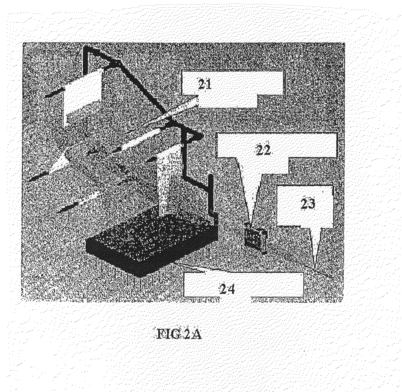
[0101]Commercially available 48- and 96-capillary arrays from ABI (Part nos. 4331250 and 4305787 from Applied Biosystems, Calif., USA) were used as a model system for our experimental studies (see FIG. 2). In both arrays the detection cell comprises capillaries aligned with silicon V-groves and immersed in a refractive index liquid with n1=1.2925.

[0102]In our experiments the 48-capillary array represented a structure without insertions and the 96-capillary array was used to model a 48-capillary array with composite insertions. Odd-numbered capillaries of the 96-capillary array were filled with separation polymer POP-7 (ABI P / N 4352759) and even-numbered capillaries contained a refractive index liquid with a certain value of n′3. The detection cell was modified to allow the replacement of the original refractive index liquid with a fused-silica matching liquid to exactly match the refractive index of capillary walls. Since the period of the 96-capillary array is equal to the outer di...


PUM


Abstract

The invention relates to devices that contain linear channels having optically transparent substances for focusing light. In some embodiments, the invention relates to improved nucleic acid sequencing methods using devices disclosed herein. In other embodiments, the invention relates to the arrangement of materials in and around capillary tubes with refractive indexes that maximize the number of channels useful for fluorescent detection of compositions after capillary electrophoresis.

Description

CROSS-REFERENCE TO RELATED APPLICATION[0001]This application claims the benefit of provisional U.S. Appln. No. 60 / 707,664, filed Aug. 11, 2005, incorporated herein in its entirety.FIELD OF INVENTION[0002]The invention relates to devices that contain linearly aligned channels comprising optically transparent elements comprising substances or materials for transmitting and focusing light. In some embodiments, the invention relates to improved nucleic acid sequencing methods using devices disclosed herein. In other embodiments, the invention relates to the arrangement of materials in and around capillary tubes, the materials having refractive indexes that maximize the number of channels useful for fluorescent detection of compositions after capillary electrophoresis.BACKGROUND[0003]In linear multicapillary array-based DNA sequencing machines, a laser beam irradiates individual capillaries of the array, and a multipixel photodetector collects the resulting fluorescence of fluorophore-la...

Claims


Application Information

Patent Timeline
IPC IPC(8): G01D5/30G02B27/12G06F17/10G01N21/05
CPCG01N27/44721
Inventor GORFINKEL, VERAGORBOVITSKI, MICHAELTSUPRYK, ANDRIY
Owner THE RES FOUND OF STATE UNIV OF NEW YORK
Why Eureka
Try Eureka