Coil substrate structure, substrate holding structure, and switching power supply

a technology of holding structure and coil substrate, which is applied in the direction of electric variable regulation, process and machine control, instruments, etc., can solve the problems of difficult to mount components with a large amount of heat generation on this area, and achieve the effect of preventing warp and flexure, preventing the circuit substrate from vibrating, and enhancing the adhesion between the circuit substrate and the chassis

Active Publication Date: 2010-07-01
TDK CORPARATION
View PDF1 Cites 46 Cited by
  • Summary
  • Abstract
  • Description
  • Claims
  • Application Information

AI Technical Summary

Benefits of technology

[0021]In this substrate holding structure, the pressing member presses the mounted component, whereby the circuit substrate is pressed in its thickness direction against the chassis. The through member penetrates through the circuit substrate, while the circuit substrate is inhibited from shifting along the main face thereof (hereinafter simply referred to as “shifting”) by the through member alone. Therefore, the circuit substrate is secured to the chassis while being allowed to shift by a gap with the through member. Hence, the stress generated in the circuit substrate can be released, so as to prevent the warp and flexure from occurring, whereby the adhesion between the circuit substrate and chassis can be enhanced. This can inhibit the circuit substrate from vibrating and favorably transfer the heat from the circuit substrate to the chassis. Since the through member constitutes the predetermined circuit, it is not necessary to provide a fastening device such as a screw or pin separately at the time of securing the circuit substrate, whereby the mounting area can be kept from being reduced by such a fastening device. As a result, the present invention can enhance the adhesion between the circuit substrate and chassis while securing the mounting area.
[0022]A specific structure which favorably yields the advantageous effect mentioned above is one in which the through member penetrates through the circuit substrate with a predetermined amount of gap. The circuit substrate may comprise a first coil substrate having a primary trans

Problems solved by technology

Here, the area where the first and second coil substrates overlap each other is an area where the primary and secondary transformer coil parts overlap each other as seen in the substrate

Method used


Image

  • Coil substrate structure, substrate holding structure, and switching power supply
  • Coil substrate structure, substrate holding structure, and switching power supply
  • Coil substrate structure, substrate holding structure, and switching power supply

Examples


first embodiment

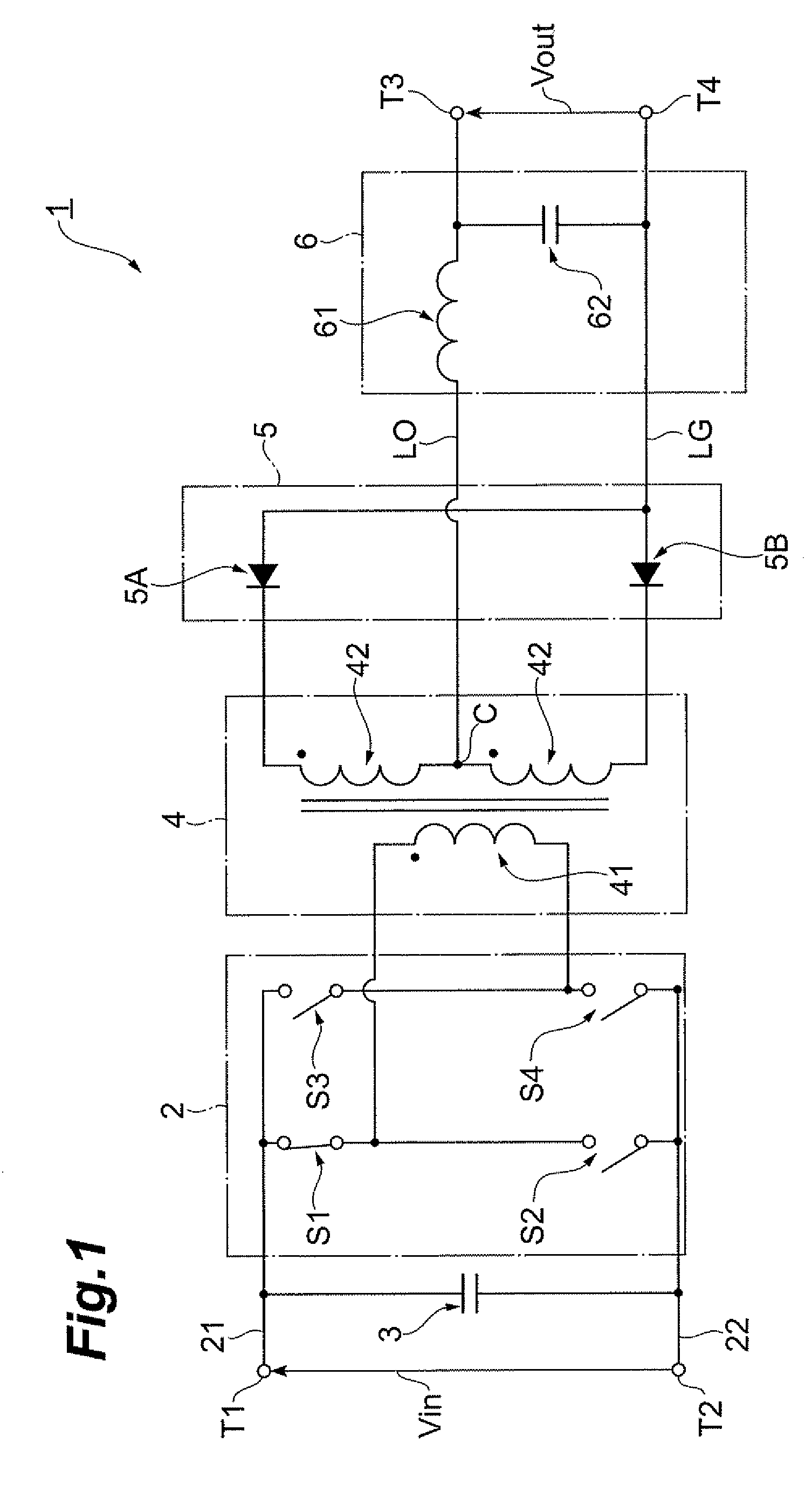
[0042]FIG. 1 is a circuit diagram of the switching power supply in accordance with the first embodiment of the present invention. As illustrated in FIG. 1, the switching power supply 1 in accordance with this embodiment, which functions as a DC to DC converter, converts a higher DC input voltage Vin supplied from a higher voltage battery or the like into a lower DC output voltage Vout and feeds the latter to a lower voltage battery or the like.

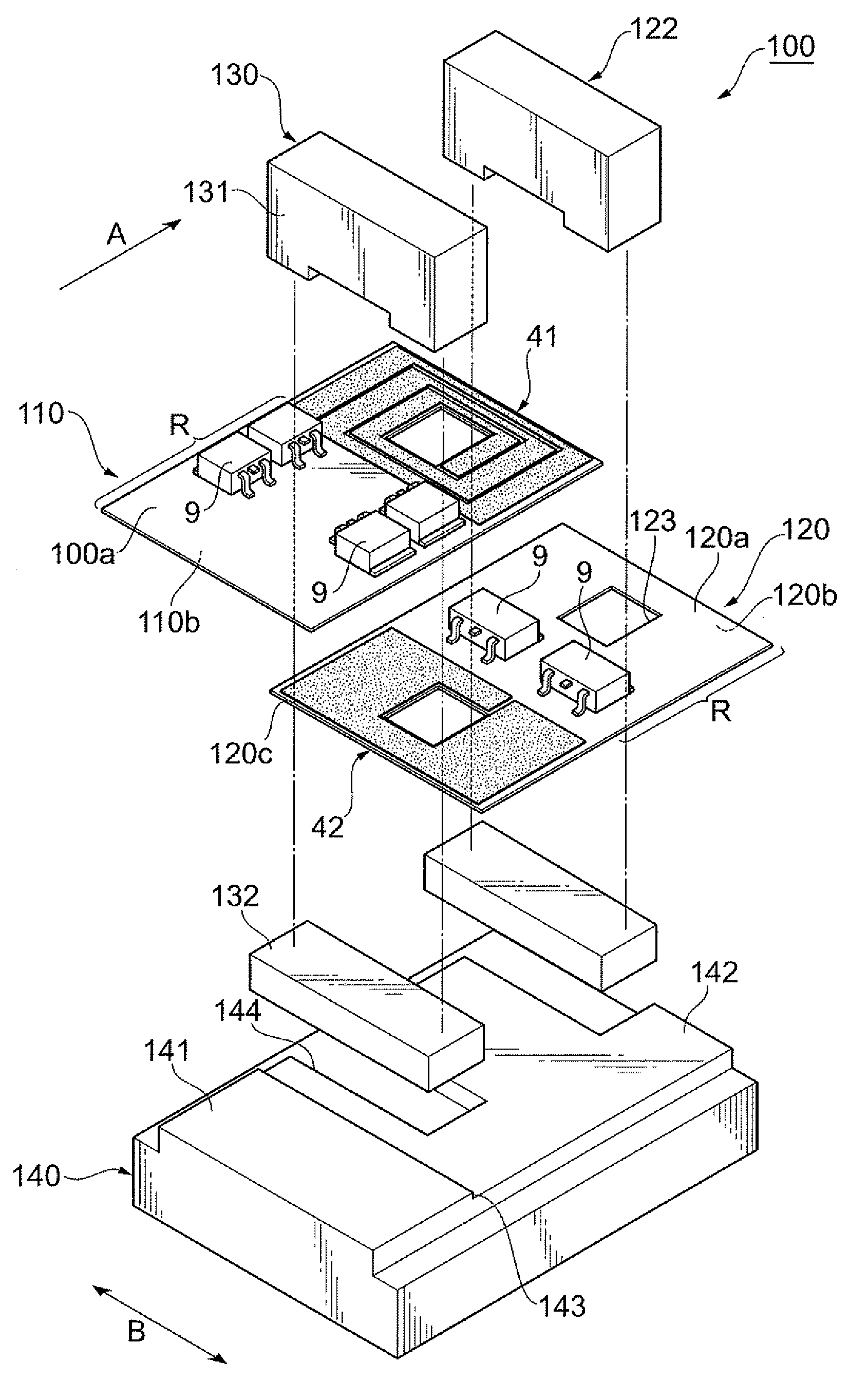
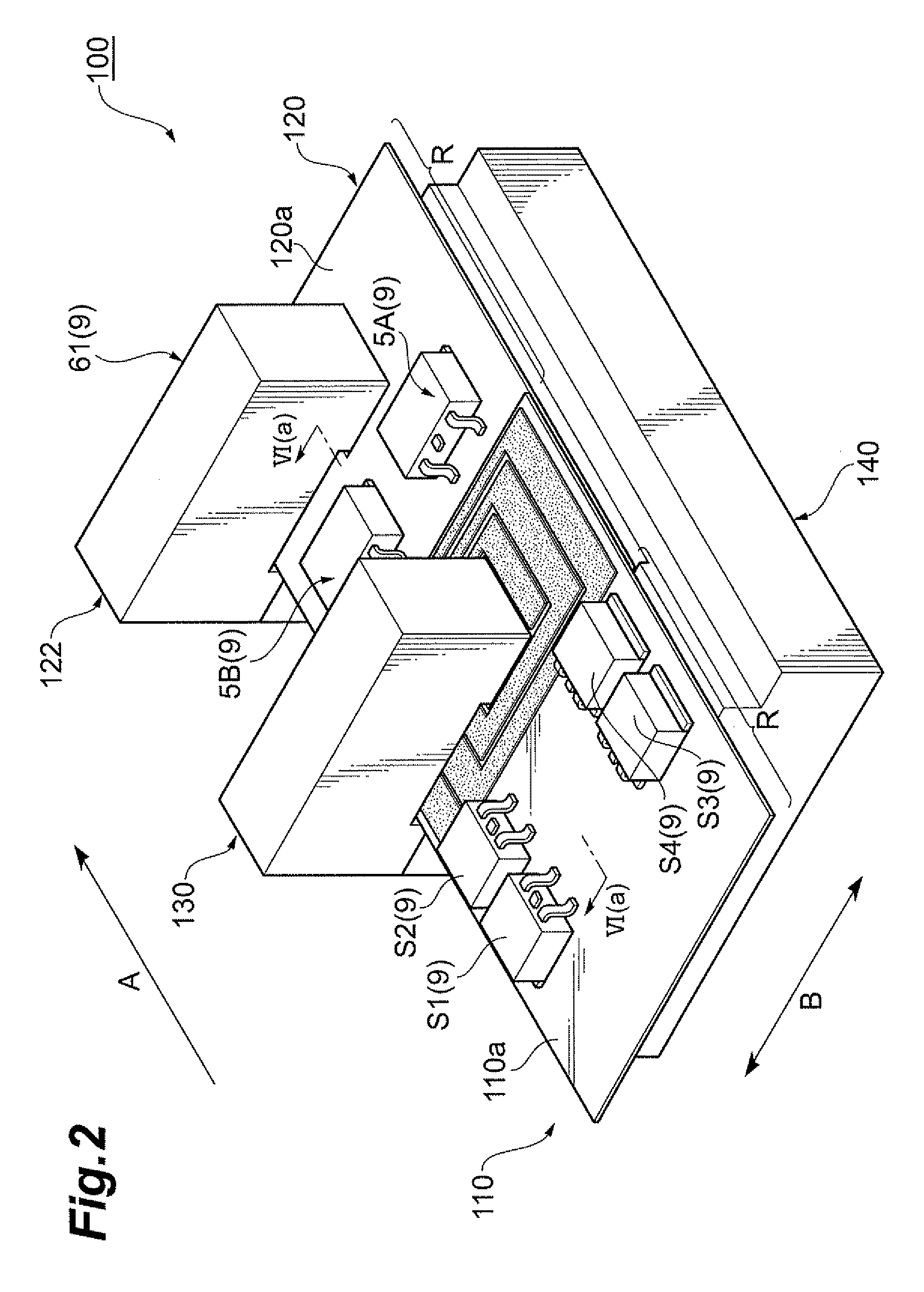
[0043]The switching power supply 1 comprises a switching circuit 2 and an input smoothing capacitor 3 which are disposed between a primary higher voltage line 21 and a primary lower voltage line 22, a transformer 4 having primary and secondary transformer coil parts 41, 42, a rectifier circuit 5 connected to the secondary transformer coil part 42, and a smoothing circuit 6 connected to the rectifier circuit 5.

[0044]The switching circuit 2 has a full-bridge circuit structure constituted by switching devices Si to S4. In response to a driving si...

second embodiment

[0089]FIG. 8 is a circuit diagram of the switching power supply in accordance with the second embodiment of the present invention. As illustrated in FIG. 8, the switching power supply 301 in accordance with this embodiment, which functions as a DC to DC converter, converts a higher DC input voltage Vin supplied from a higher voltage battery or the like into a lower DC output voltage Vout and feeds the latter to a lower voltage battery or the like.

[0090]The switching power supply 301 comprises a switching circuit 32 and an input smoothing capacitor 33 which are disposed between a primary higher voltage line 321 and a primary lower voltage line 322, a transformer 34 having primary and secondary transformer coil parts 341, 342, a rectifier circuit 35 connected to the secondary transformer coil part 342, and a smoothing circuit 36 connected to the rectifier circuit 35.

[0091]The switching circuit 32 has a full-bridge circuit structure constituted by switching devices S31 to S34. In respo...


PUM


Abstract

A coil substrate structure which enhances heat dissipation and fully secures a mounting area is provided. A coil substrate structure 100 comprises a first coil substrate 110 having a primary transformer coil part 41; a second coil substrate 120, disposed on the first coil substrate 110, having a secondary transformer coil part 42; and a transformer core 130 for magnetically connecting the transformer coil parts 41, 42 to each other. The coil substrates 110, 120 are disposed on each other while being shifted from each other such that the transformer coil parts 41, 42 overlap each other as seen in the substrate thickness direction. This can increase the heat dissipation area of the coil substrates 110, 120. The transformer coil parts 41, 42 have a width in a transmission direction A narrower than a width in a direction B intersecting the transmission direction A as seen in the substrate thickness direction. This can reduce the multilayer area of the coil substrates 110, 120 in the transmission direction A.

Description

BACKGROUND OF THE INVENTION[0001]1. Field of the Invention[0002]The present invention relates to a coil substrate structure, a substrate holding structure, and a switching power supply.[0003]2. Related Background Art[0004]Known as a conventional coil substrate structure is one comprising a first coil substrate having a primary transformer coil part, a second coil substrate having a secondary transformer coil part, and a transformer core for magnetically connecting the primary and secondary transformer coil parts to each other (see, for example, Japanese Patent Application Laid-Open No. 2005-38872). The first and second transformer coil parts in such a coil substrate structure are disposed on each other such that the primary and secondary transformer coil parts overlap each other as seen in the substrate thickness direction.[0005]Known as a conventional substrate holding structure is one comprising a circuit substrate, a chassis mounted with the circuit substrate, components mounted ...

Claims


Application Information

Patent Timeline
IPC IPC(8): H01F5/00
CPCH01F27/22H01F27/2804H01F27/306H05K1/144H05K1/165H05K2201/086H05K2201/09063
Inventor NAKAHORI, WATARUKAN, MASAKIYAKUWA, ATSUSHI
Owner TDK CORPARATION
Why Eureka
Try Eureka