Image processing apparatus, printing apparatus, and image processing method

Active Publication Date: 2010-07-01
CANON KK
View PDF11 Cites 7 Cited by
  • Summary
  • Abstract
  • Description
  • Claims
  • Application Information

AI Technical Summary

Benefits of technology

[0026]An object of the present invention is to provide an image processing apparatus, a printing apparatus, and an image processing method which enables generation of print data with reducing a processing load as much as possible and capable of enhancing robustness.
[0030]According to the above configuration, division and gradation lowering of an image are carried out not only by a first processing effective in robustness but also by a second processing, in accordance with channel information specifying the image. Thereby, an increase of the processing load by executing the first processing is eliminated as much as possible, to make print data, which is capable of appropriately enhancing robustness in accordance with the image, generated.

Problems solved by technology

These variations appear as variations of ejection characteristics such as an ejection amount or an ejection direction of ink to produce irregular shapes of dots formed on the print medium, as a result possibly creating uneven density or stripes on an image.
Therefore, it is difficult to always evenly distribute such a print data to the plurality of scans or plurality of printing element lines by using a mask pattern in which a pattern of the print permitting pixels is previously defined.
Even if the above multi-pass system is employed, under recent situations where a higher-quality printing is demanded, a density change or an uneven density due to a shift of a print position (registration) in a scan unit or in a nozzle line unit is seen newly as a problem.
Specifically, when the shift between the planes changes with the fluctuation in the distance between the print medium and the ejection opening surface (the distance from a sheet) or the fluctuation in the conveying amount of the print medium, the density of the uniform image also changes with these fluctuations, which results in being recognized as density unevenness.
However, in the print data generation method described in Japanese Patent Laid-Open No. 2000-103088 or Japanese Patent Laid-Open No. 2006-231736, since it is, as shown in an example in FIG. 4, necessary to perform quantization or gradation lowering process (binarization in an example in FIG. 4) for each of plurality of divided image data, there exists a problem that the processing load increases.
For meeting demands for the high quality, the multi-color and the printing to a large scale of sheet, however, there occurs the problem that the image processing is complicated and a circuit scale or a memory capacity increases in proportion to the number of colors or print width and also the cost increases.
In addition, high speed of the printing speed increases a load of the image processing and also increases costs.
Under these circumstances, performing the quantization to each divided image further causes an increase in the processing load.

Method used


Image

  • Image processing apparatus, printing apparatus, and image processing method
  • Image processing apparatus, printing apparatus, and image processing method
  • Image processing apparatus, printing apparatus, and image processing method

Examples


first embodiment

[0048]FIG. 6 is a perspective view explaining a schematic structure of a serial type inkjet printing apparatus used in a first embodiment of the present invention. A print head 105 is mounted on a carriage 104 that moves at a constant speed in a main scan direction and ejects ink according to print data in a frequency corresponding to the constant speed. When one time of scan is completed, a conveying roller 704 and an auxiliary roller 703 rotate and a print medium P held between these rollers and between a feeding roller 705 and an auxiliary roller 706 is conveyed in a sub scan direction by an amount corresponding to a print width by the print head 105. This scan and the conveying operation are intermittently repeated to print an image on the print medium P step by step.

[0049]The print head 105 includes print heads of black (K), cyan (C), magenta (M) and yellow (Y) which are located in a main scan direction shown in the figure and plurality of ejection openings are arranged in a su...

second embodiment

[0076]A second embodiment of the present invention relates to the processing of image data of channels distinguished based on an ink ejection amount and executes the processing similar to the process shown in the image processing shown in FIG. 8 in the printing apparatus shown in FIG. 6 of the above first embodiment.

[0077]FIG. 11 is a flow chart showing the processing executed by the channel selection section 803 in the present embodiment. As shown in this figure, the channel selection section 803 determines at step S901 whether or not a channel of the image data for which the selection is executed is a channel of the ink ejection amount that is previously set. In the present embodiment, three kinds of ink ejection amounts of 1 pl, 1.5 pl and 2 pl are possible. Specially in a case of performing a printing operation using respective print heads (or respective ejection opening lines) of an ejection amount of 1 pl, 1.5 pl or 2 pl, the processing in the image processing section 603 gene...

third embodiment

[0081]A third embodiment of the present invention relates to a printing apparatus using a full line type print head in which two print heads perform the print operation similar to the multi-pass printing.

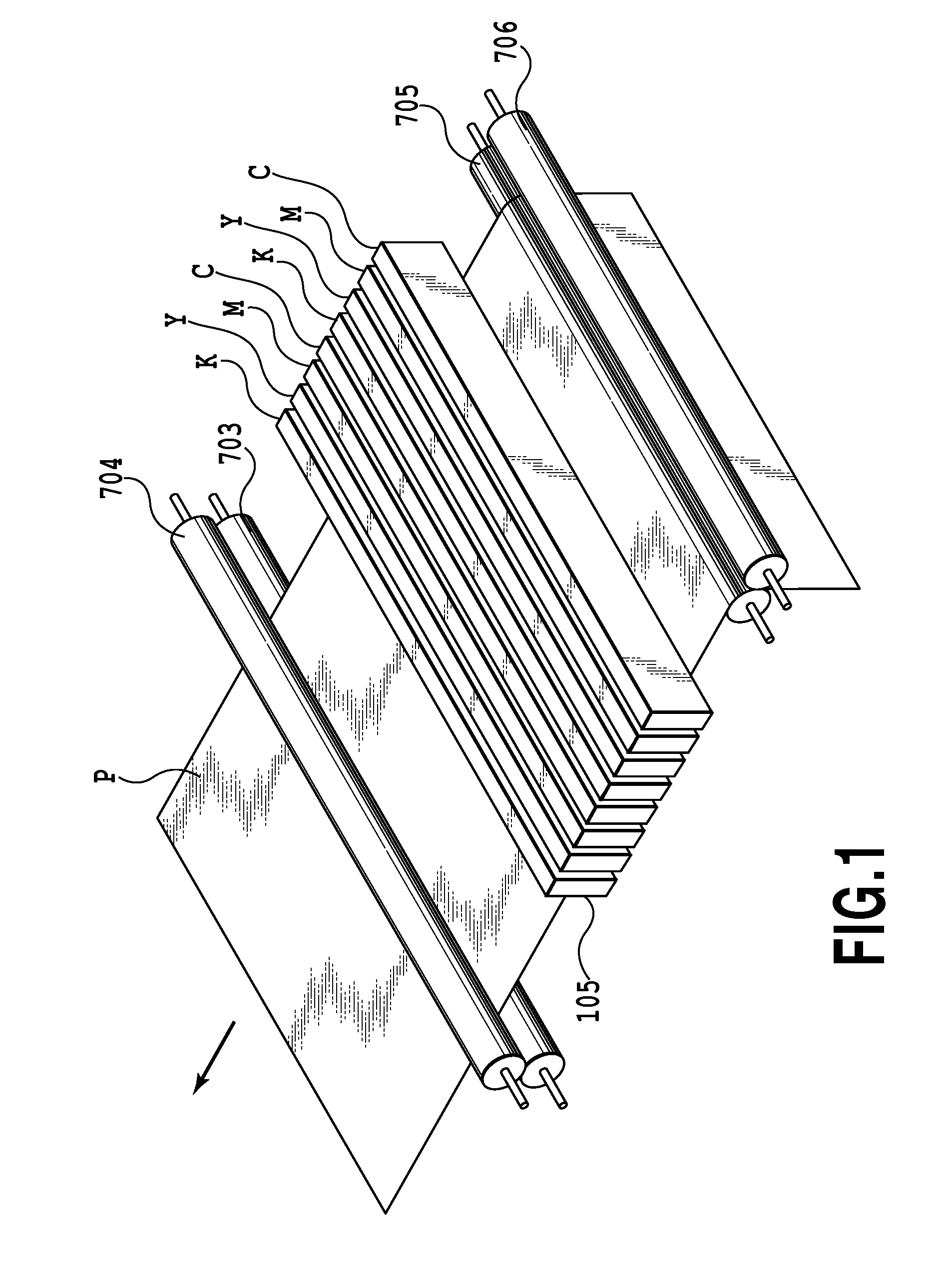
[0082]FIG. 1 shows the general construction of a full line type inkjet printing apparatus according to the present embodiment. In FIG. 1, after the print medium P receives a sheet fed by the feeding roller 705 and the auxiliary roller 706, the print medium P is conveyed in the direction of the feeding roller 704 and the auxiliary roller 703 and is conveyed in a sub scan direction at a predetermined speed while being held by the two pairs of the rollers. Ink is ejected onto the print medium to be thus conveyed from respective ejection openings of the print head 105 arranged in a main scan direction, at a certain frequency corresponding to the conveying speed of the print medium. The print head 105 includes the full line type print heads for ejecting ink of cyan (C), magenta (M), yell...


PUM


Abstract

A channel selection section selects whether the subsequent processing to the image data is executed by image distribution precedence processing or by gradation lowering precedence processing in accordance with channel information of the image data. That is, in regard to the channels of C, M and K with relatively high density among inks, the image distribution precedence processing excellent in robustness is selected. On the other hand, in the ink of the color with high brightness or low density, even if the print position of the dot is shifted, the density change due to this shift is not so much large. It is possible to restrict an increase in the processing load due to executing the gradation lowering processing after the distribution processing to each of the plural divided images by thus not selecting the image distribution precedence processing in consideration of the robustness.

Description

BACKGROUND OF THE INVENTION[0001]1. Field of the Invention[0002]The present invention relates to an image processing apparatus, a printing apparatus, and an image processing method, and particularly, to a print data generating configuration that enables an image print to have a tolerance for image quality degradation against variations of print characteristics between printing elements of a print head, a fluctuation in scanning of the print head, a conveying error of a print medium and the like.[0003]2. Description of the Related Art[0004]As an example of a printing system using a print head provided with a plurality of printing elements, there is known an inkjet print system which ejects ink from an ejection opening as the printing element to form dots on a print medium. Such an inkjet printing apparatus is classified into a full line type and a serial type depending particularly on a difference in construction of the print head.[0005]The full line type printing apparatus is provid...

Claims


Application Information

Patent Timeline
IPC IPC(8): G06F15/00B41J29/38
CPCH04N1/23H04N1/405
Inventor NAKAMURA, HIRONORIHORIKOSHI, HIROKIFUJIMOTO, YASUNORIMIYAZAKI, SHINICHIICHIMURA, AKIRA
Owner CANON KK
Why Eureka
Try Eureka