
Air compressor

a technology of air compressor and air filter, which is applied in the direction of positive displacement liquid engine, pump components, piston pump, etc., can solve the problems of shrinking blood vessels, damage to human bodies, and the noise of conventional air compressor operation is often great, so as to achieve convenient maintenance and efficient replacement

Inactive Publication Date: 2010-07-01
LO AN SHUN +1
View PDF14 Cites 2 Cited by
  • Summary
  • Abstract
  • Description
  • Claims
  • Application Information

AI Technical Summary

Benefits of technology

[0005]The primary objective of the present invention is to provide an air compressor that features easy maintenance and is noise free in the operation thereof.
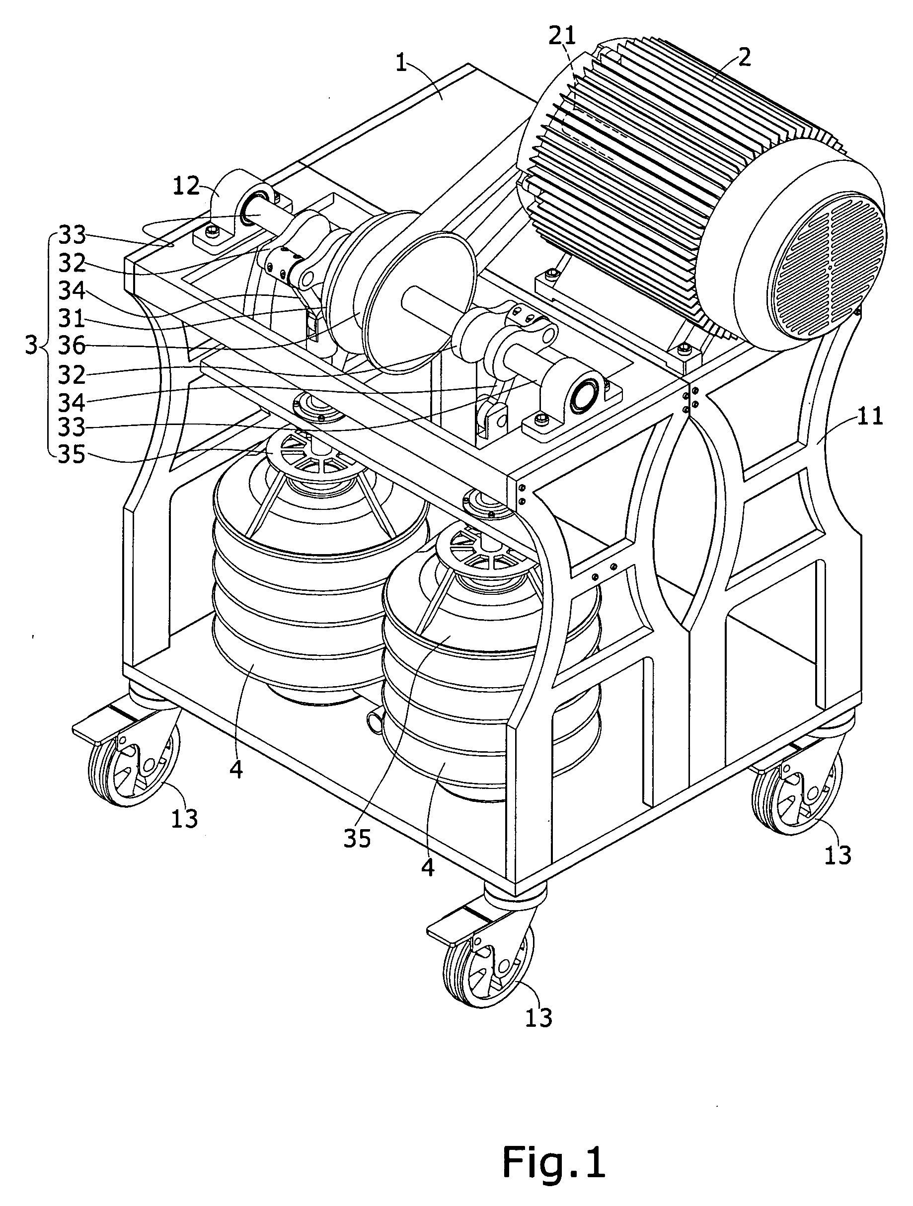
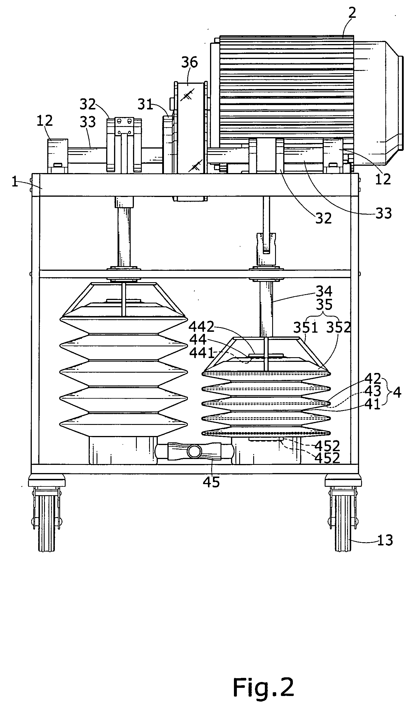
[0007]In the operation of the present invention, the mechanical power generated by the operation of the motor is used to drive the rotation of the whole transmission set, causing the crank arms to move for inducing reciprocal motion that drives reciprocal and axial compression operation of the extendible barrels, whereby air is drawn into the extendible barrels through the air inlet ports, compressed by the extendible barrels, and then discharged through the air outlet ports of the extendible barrels as compressed air. The extendible barrels adopted in the present invention are resilient and elongation resisting, so that no noise will be generated during the operation of the present invention and efficient replacement and convenient maintenance can be quickly done when malfunctioning occurs.

Problems solved by technology

However, a conventional air compressor often generates a great noise during its operation, and this is basically due to the mechanical structure thereof.
Such a high noise often causes damage to human body, such as shrinkage of blood vessel, increase of blood pressure, dizziness, and being easily irritated.
This solution, however, does not realize eliminate the noise problem induced by the conventional air compressor, for it can at most lower the noise level and improve heat dissipation.

Method used


Image

  • Air compressor
  • Air compressor
  • Air compressor

Examples


Embodiment Construction

[0018]The following descriptions are exemplary embodiments only, and are not intended to limit the scope, applicability or configuration of the invention in any way. Rather, the following description provides a convenient illustration for implementing exemplary embodiments of the invention. Various changes to the described embodiments may be made in the function and arrangement of the elements described without departing from the scope of the invention as set forth in the appended claims.

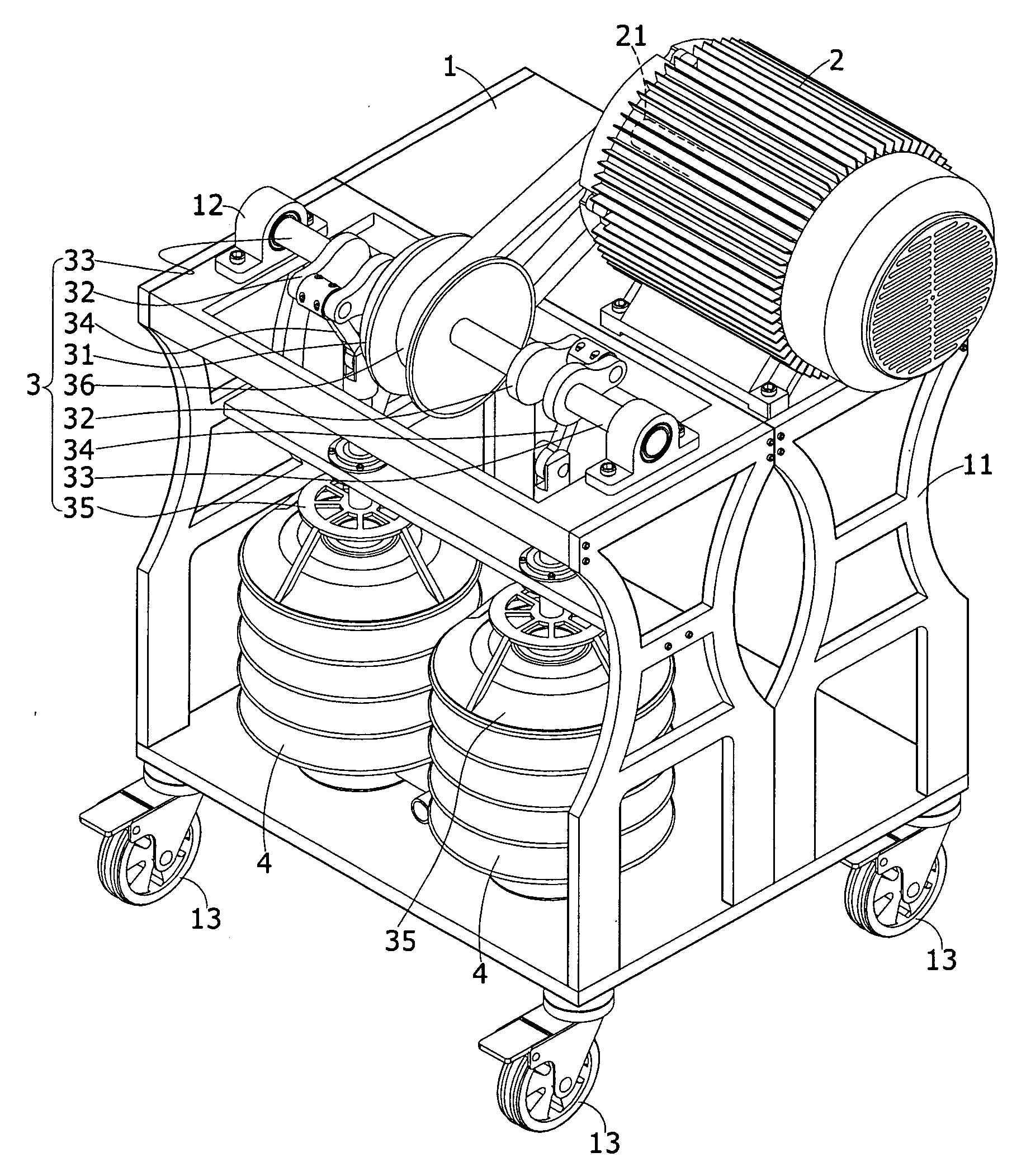
[0019]With reference to the drawings and in particular to FIGS. 1 and 2, an air compressor constructed in accordance with a preferred embodiment of the present invention comprises a chassis 1, which is comprised of a plurality of frames 11. The chassis 1 forms a bearing seat 12 at a suitable location on each of opposite side portions thereof. Each bearing seat 12 contains therein bearing means that supports rotation. The chassis 1 has a bottom to which a plurality of casters 13 is mounted.

[0020]A mo...


PUM


Abstract

An air compressor includes a chassis that supports thereon a motor, a transmission set, and a plurality of extendible barrels. The transmission set includes a clutch that is operatively coupled to the motor through a belt. Two eccentric rotation members are respectively arranged on opposite sides of and coupled to the clutch. Each eccentric rotation member is coupled to a crank arm, which has a moving end connected to the extendible barrel. The extendible barrel is provided with an air inlet port and an air outlet port. When the motor is set in operation, the transmission set drives the extendible barrels to move carry out reciprocal and axial compression to delivery compressed air. The present invention features easy maintenance and can carry out a noise-free operation.

Description

TECHNICAL FIELD OF THE INVENTION[0001]The present invention generally relates to an air compressor that generates pressurized air, and particularly to an air compressor that comprises eccentric rotation members that are set in rotation to cause reciprocal compression of extendible barrels for realizing noise-free operations.DESCRIPTION OF THE PRIOR ART[0002]Pressurized air is advantageous in low costs and low pollution in providing mechanical power. Thus, it is widely used to actuate pneumatic devices, pneumatically operated tools or to smooth the operation of machines. An air compressor is often employed to convert atmospheric air into pressurized air and the operation of the air compressor is that a motor is used to drives a piston to reciprocate inside a cylinder for drawing air into the cylinder and to compress the air into pressurized air for direct use or storage in a high-pressure air canister. With the evolution of techniques, various pneumatic tools are available in the mar...

Claims


Application Information

Patent Timeline
IPC IPC(8): F04B45/02
CPCF04B39/0022F04B39/0027F04B9/045F04B27/02F04B45/022F04B45/024
Inventor LO, AN-SHUNHSIEH, YING-PO
Owner LO AN SHUN
Learn More