Method for Examining an Ice Region or Dry Region Using Radar Echo Sounding

a radar echo and ice technology, applied in the direction of instruments, measurement devices, antennas, etc., can solve the problems of increasing hardware effort in the design and construction of the antenna, not substantially attenuating the so-called “cross ambiguities” of the known method, and reducing the useful signal coming from the direction of the nadir. to the upper ice layer. , to achieve the effect of improving the echo sounding properties

Active Publication Date: 2010-07-08
DEUTSCHES ZENTRUM FUER LUFT & RAUMFAHRT EV
View PDF23 Cites 16 Cited by
  • Summary
  • Abstract
  • Description
  • Claims
  • Application Information

AI Technical Summary

Benefits of technology

[0025]The method for examining an ice region or a dry region using radar echo sounding according to the present invention offers a number of advantages.
[0028]The method according to the invention provides a perfect, exact echo sounding in the direction of the nadir and thus an increased sensitivity to the detection of inner ice sheets or dry layers as well as to reflections from the bedrock.
[0029]The performance of the ambiguity suppression is scalable in dependence on the number of available recordings / overpasses. A first suppression of ambiguities is already obtained from three overpasses. For space-borne systems, an improved suppression of ambiguities can be achieved, including suppression of the PRF range ambiguity caused by the pulse repetition frequency (PRF).
[0033]Besides an application in radar systems for echo sounding in ice, the method operating according to the invention is also suited for echo sounding in dry regions of the earth and other planets ad extraterrestrial objects where substantial penetration depths are desired. On earth, this may allow the detection of antique settlements covered by sand or of old riverbeds in desert regions. When the method of the present invention is applied to planets, his method will enhance the detection of craters or ice sheets covered by sand or sediments as well as of further morphological features.

Problems solved by technology

However, these known methods do not substantially attenuate the so-called “cross ambiguities” coming from the left and the right side of the flight path (across track). FIG. 1 serves for clarification of this context, schematically illustrating the geometry across the direction of flight of a nadir-directed radar beam for echo sounding in ice.
Thereby, the depth up to which ambiguity signals superimpose the useful signal coming from the direction of the nadir is limited to the upper ice layers.
Moreover, an increased hardware effort is required in the design and construction of the antenna, especially when more than two apertures are needed.
For instance, the increased attenuation of the electromagnetic wave in the ice sheet may possibly make the detection of the bedrock considerably more difficult because of the of-nadir geometry.
Moreover, reflections from inner ice sheets may possibly also be hard to detect in an off-nadir geometry.
Since the interferometric spectral components for ice surfaces and bedrock approach each other more closely with thin ice thicknesses, the discrimination between these two signal components is limited in this instance.
Finally, the suppression of ambiguities is difficult for signal components of the respective opposite off-nadir side, since the signals generally do not superpose each other coherently.

Method used


Image

  • Method for Examining an Ice Region or Dry Region Using Radar Echo Sounding
  • Method for Examining an Ice Region or Dry Region Using Radar Echo Sounding
  • Method for Examining an Ice Region or Dry Region Using Radar Echo Sounding

Examples


Embodiment Construction

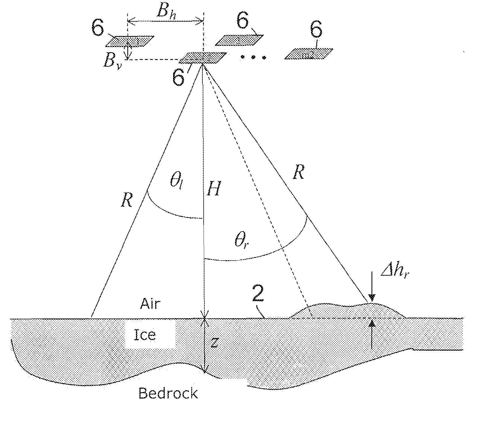
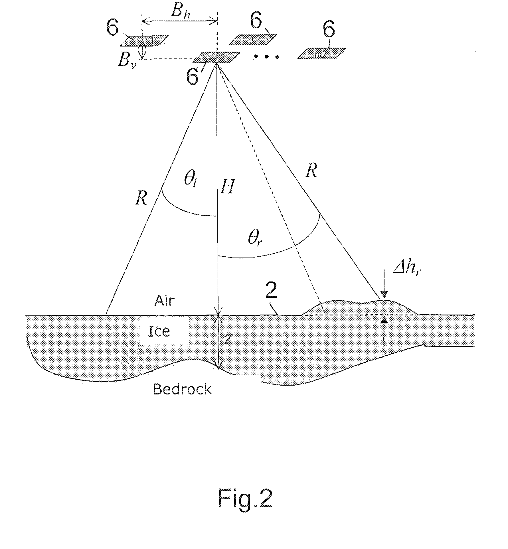
[0043]FIG. 2 is a schematic illustration of the radiation geometry of a nadir-oriented radar sensor 6 for echo sounding in ice. The direction of flight of the airplane- or space-borne radar sensor 6 is perpendicular to the plane of the drawing. Ambiguities transverse to the direction of flight superpose the interesting echo signal coming from the direction of the nadir. Because of the topography of the region to map, the geometry is generally not symmetric.

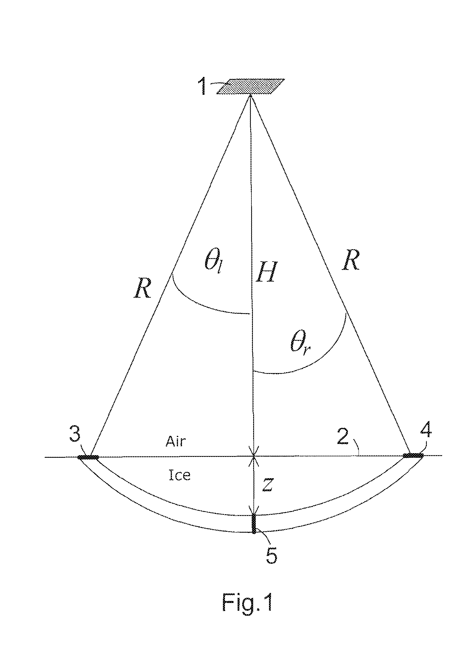
[0044]Due to physical and technical limits, the antenna aperture can not be large and thus sufficiently focussing to illuminate only the nadir region. Consequently, signals from the right and the left of the ground track are captured by the main lobe of the antenna. This fact has already been explained in the context of the description of FIG. 1 in which the same geometric numerals have been used as are now used in FIG. 2.

[0045]The multiple illustration of the radar sensor 6 is to symbolize that several spatially offset overpasses...


PUM


Abstract

To suppress cross-ambiguities in the examination of an ice region or dry region by means of aircraft- or aerospace-supported radar echo sounding, the region to be examined is overflown by a radar sensor (6) by multiple compatible radar sensors of the same operating wavelength on multiple spatially separated, substantially parallel paths, wherein the radar signal data received on each path are recorded. The radar signal data recorded for each of the different paths are summed coherently and using a weighting to form a radargram, wherein an adaptive complex-valued weighting for each of the individual paths is performed using a geometrical model which takes into account the topography of the environment of the region to be examined. The weighting for every depth of the examined region is determined by solving a system of linear equations from which is calculated a synthetic antenna pattern which has zeros in the direction of the ambiguities.Implementation in radar systems for echo sounding in ice and in dry regions on earth or other planets and extraterrestrial objects.

Description

TECHNICAL FIELD[0001]The invention is directed to a method for examining an ice region or dry region using radar echo sounding, wherein a radar sensor flying over the region to be examined emits radar transmission pulses in the direction of the nadir, illuminating the surface and the inner volume of the region, wherein the reflected radar pulse signals received in the radar sensor are processed and evaluated to obtain a radargram, and wherein measures are provided to suppress ambiguities.[0002]An explanation of the general operation of a radar method for echo sounding in ice will be rendered hereunder. Such radar methods have been used for more than two decades in Antarctica, Greenland and on other smaller islands, such as Spitsbergen-Svalbard, to derive information about ice layers, ice thicknesses as well as the bedrock of the ice plates. The information derived consists of a depth profile of the ice mass and is generally referred to as a radargram. It includes the radar reflectiv...

Claims


Application Information

Patent Timeline
Patent Type & Authority Applications(United States)
IPC IPC(8): G01S13/00G01S13/935
CPCG01S7/2813G01S13/882H01Q3/2611G01S2013/9047G01S13/9035G01S13/904G01S13/9047
Inventor SCHEIBER, ROLF
Owner DEUTSCHES ZENTRUM FUER LUFT & RAUMFAHRT EV
Why Eureka
Try Eureka