Retractable wind turbines

a wind turbine and rotor technology, applied in the direction of rotors, sustainable manufacturing/processing, greenhouse gas reduction, etc., can solve the problems that wind turbines cannot typically handle the stresses induced, loss of production, etc., and achieve the effect of reducing noise, maximizing portability, and improving efficiency

Inactive Publication Date: 2010-07-08
SULLIVAN JOHN T
View PDF13 Cites 69 Cited by
  • Summary
  • Abstract
  • Description
  • Claims
  • Application Information

AI Technical Summary

Benefits of technology

[0007]It is an object of this invention to provide for a wind turbine electrical generating device where the blades that comprise the airfoil are collapsible during operation. This feature allows for a number of improvements over the current state of the art. Having a collapsible feature protects the turbine from damage during very heavy wind conditions, and even can keep the turbine operational to reap the power benefits of high winds. Collapsibility also enables portability by allowing for a compact device when completely retracted. Control over the retraction mechanism can be via a computer controlled feedback loop, or by mechanical means that automatically react to wind speed variations.
[0008]To enable maximum portability and light yet strong construction, the airfoil blades of the collapsible wind turbines are constructed from attached segments. In an embodiment of this invention, hollow airfoil segments are connected and built up into a large airfoil. These segments could be made of moldable plastic or wrapped with thin metal or plastic airfoils over injection molded or cast metal airfoil spacers. In another embodiment, the segments are molded spars made of a polymer or metal and utilize an outer polymer, spray coated epoxy or urethane or PVC cloth cover to create an airfoil profile shape. In another embodiment, wing tips at the ends of the blades of vertical or horizontal wind turbines are used to prevent roll off for better efficiency and reduced noise.
[0009]It is another object of this invention that airfoil blade segments are connected via a swivel joint such that the through cables can allow the blade to flex in high winds without stressing the interface between segments. In another embodiment, the interface is shaped to provide an arc in the airfoil to allow the shape of the molded sail foils to create a C-shaped profile that can flex in the wind without the stresses of flat mating surfaces. In another embodiment of this invention, the stacking airfoil segments have mating interlocking male and female end caps to provide additional structural strength. In another embodiment of this invention the airfoil segments are hinged and cables run through the segments and allow the airfoils to bend in high winds. The hinged airfoils can also act as the frame to spin the generator. Another embodiment of this invention is a method of manufacturing airfoils by inserting tubing in the plastic mold of an airfoil before foam is added to stiffen the part and to allow a cable to pass through. This method effectively encapsulates the tubing, which may be comprised of metal, fiberglass, carbon, or other material, in the foam.
[0010]It is a further object of this invention to provide for an collapsible wind generator that utilizes a plurality of airfoil units that are each comprised of concentric circles. The individual spin on each of these units enhances the revolution of their attachment arms to a central rotating shaft that powers a generator.
[0011]It is a further object of this invention to provide for an improved wind generator with flexible blades that can be extended or retracted in the manner of an umbrella. When extended, the blades flex out such that the windmill has an overall spherical shape. The individual blades have an airfoil geometry. In one embodiment, the airfoil design is such that there is an integral flap which is open to catch the wind at low speeds and is pushed into a closed position during higher wind speeds. In another embodiment, a sail is included in the interior of the sphere to enhance low speed start up.

Problems solved by technology

However there are several issues that are still being addressed to further improve performance in these devices.
One limitation of wind turbines is often an effective way of protecting the device during periods of very high wind speed.
Various braking devices and spoilers have been utilized to prevent harm to the turbine although they typically also take the turbine off-line resulting in a loss of production when the available power is the greatest.
Wind turbines cannot typically handle the stresses induced by very strong winds and so braking systems are used to stop blade rotation and avoid damage.

Method used


Image

  • Retractable wind turbines
  • Retractable wind turbines
  • Retractable wind turbines

Examples


Embodiment Construction

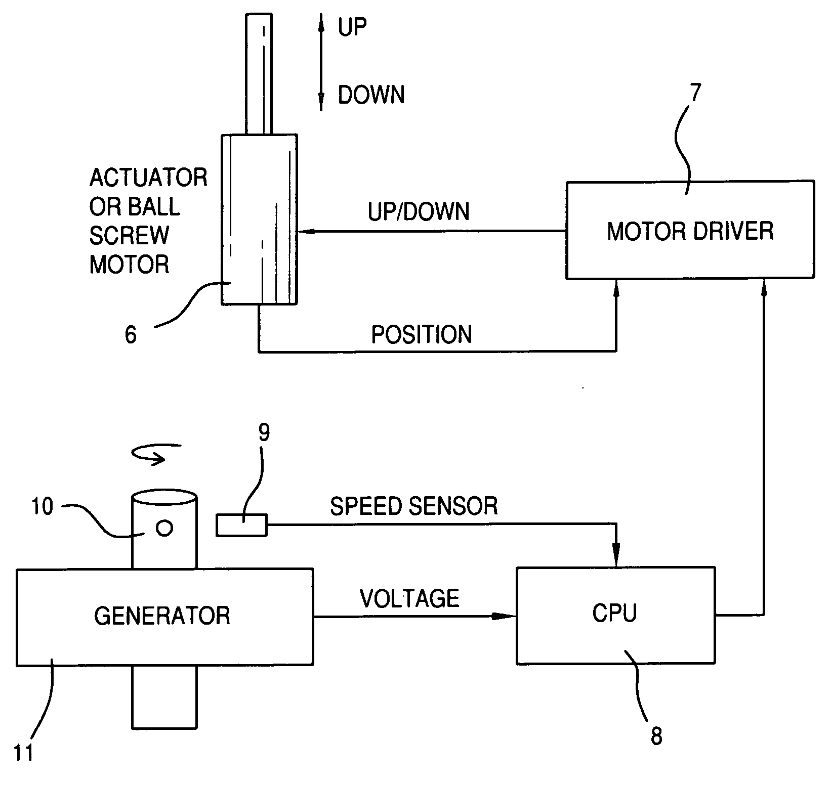
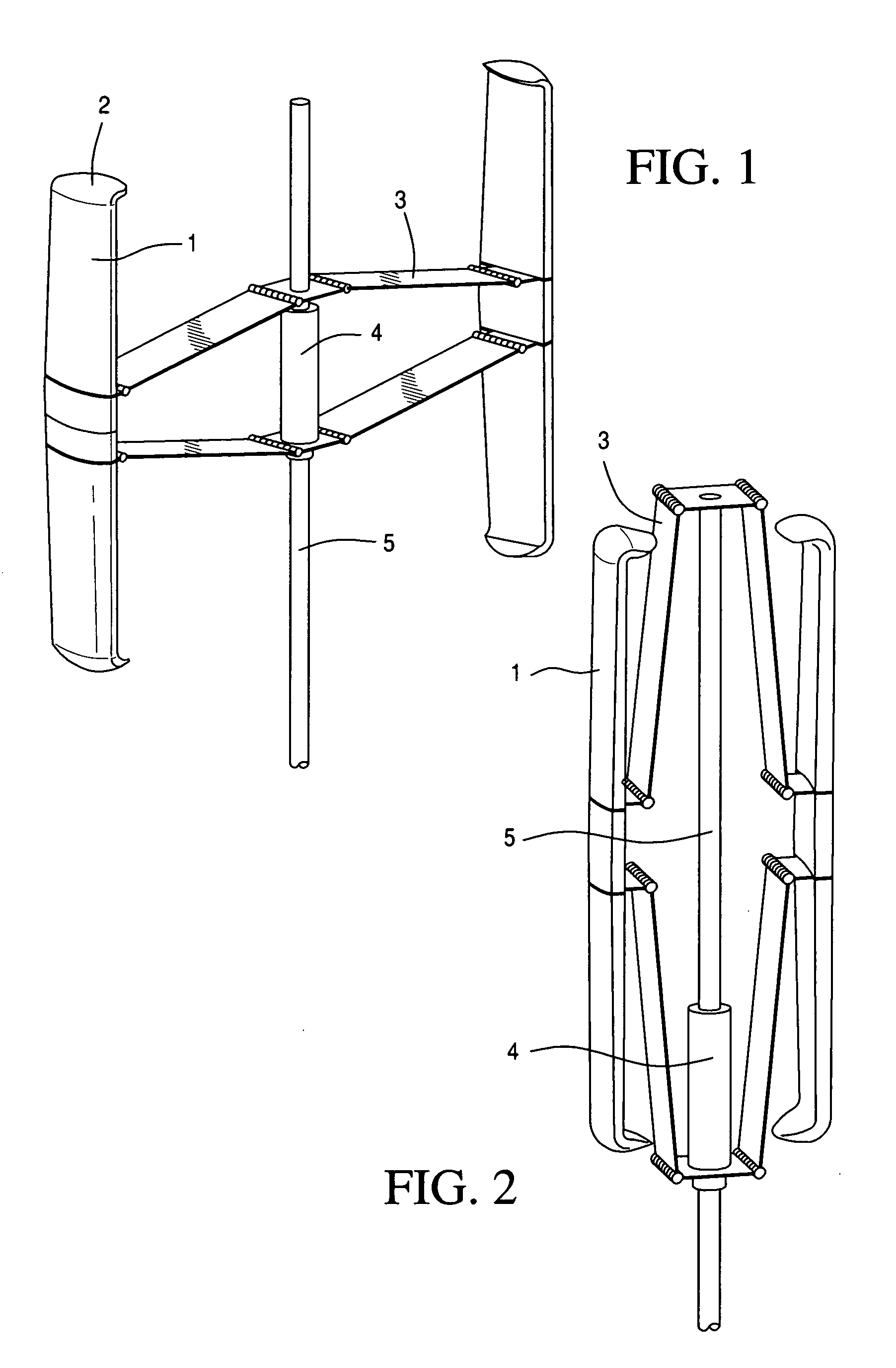
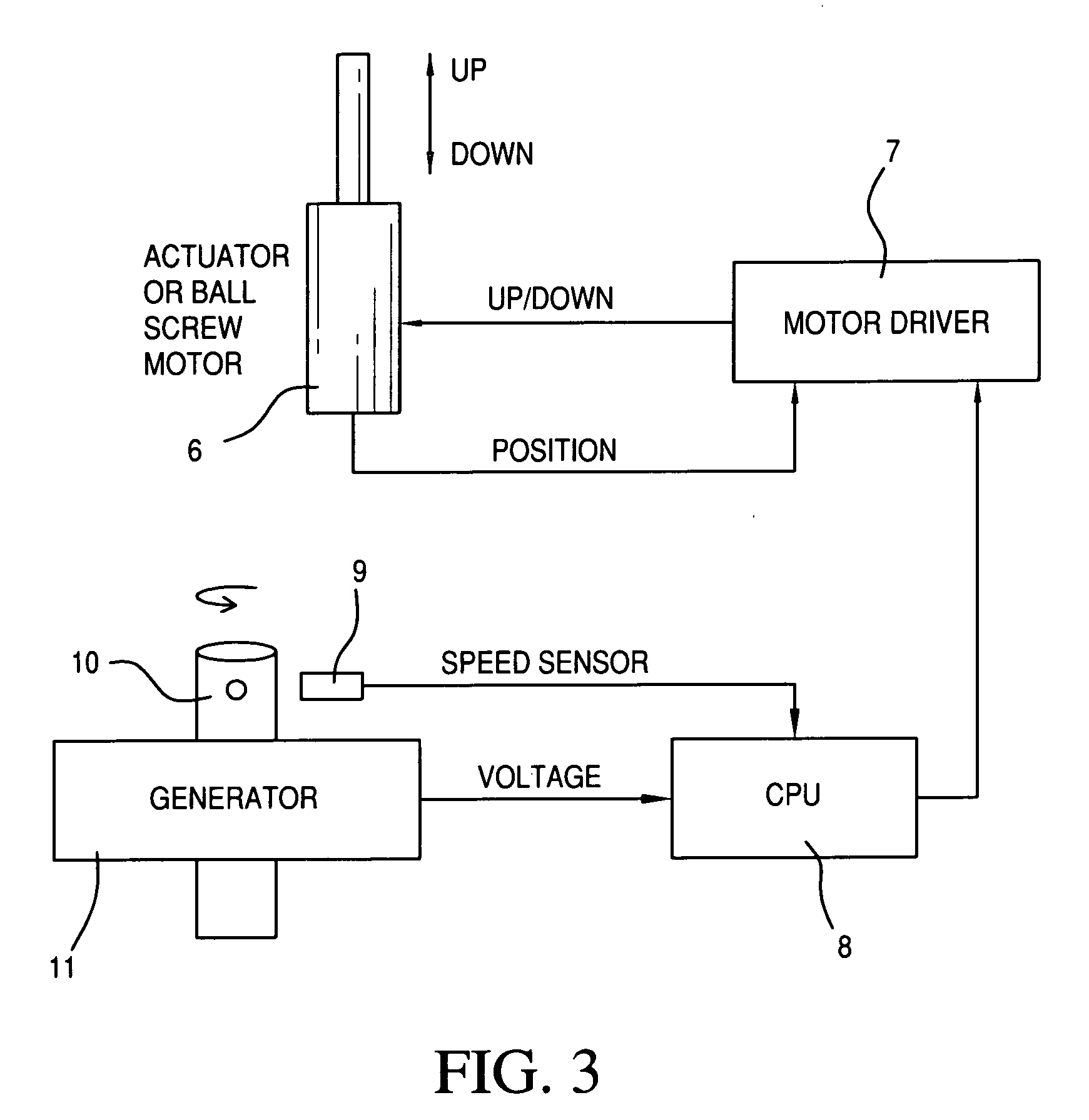
[0041]FIG. 1 shows one embodiment of this invention. In this embodiment a VAWT is built from blades comprised of segments 1 and with wing tips 2. The blades are attached by a bracket 3 that envelopes an actuator 4 that slides on the central shaft 5. The actuator moves to extend or retract the bracket depending upon wind conditions and is controlled by a torque sensor on the main shaft in a feedback loop described in FIG. 3. This type of system can also be used for VAWTs with single piece blades or without wingtips or with a different number of total blades. FIG. 2 shows the turbine during a high wind state as the actuator 4 has moved down the central shaft 5 causing the hinges on the bracket 3 to retract the blades. This retracted position protects the turbine from damage at high wind speeds yet enables it to continue spinning and supplying the generator with energy. Most wind turbines cannot operate at high wind speeds due to centrifugal forces that are damaging to the mechanical s...


PUM


Abstract

A wind turbine electrical generating device is described where the blades that comprise the airfoil are retractable during operation. This feature allows for a number of improvements over the current state of the art including damage protection and the ability to remain operational during high wind conditions. Further described is a computer feedback loop that controls the degree of retraction. In addition, lightweight airfoil turbine blades are described that are assembled from discrete segments.

Description

CROSS-REFERENCE TO RELATED APPLICATION[0001]This application claims the priority of U.S. provisional applications 61 / 204,747 filed on Jan. 8, 2009 and 61 / 216,907 filed on May 22, 2009. both of which are incorporated by reference herein in their entirety.STATEMENT REGARDING FEDERALLY SPONSORED RESEARCH OR DEVELOPMENT[0002]Not ApplicableBACKGROUND OF THE INVENTION[0003]Both horizontal and vertical axis wind turbines have been developed that display high efficiencies in converting wind power into electrical power. However there are several issues that are still being addressed to further improve performance in these devices. This invention addresses many of these issues including the ability to self start and the ability to continue operation in a high wind state in addition to improving the overall efficiency of the device. In addition, low cost manufacturing improvements and light weight methods are utilized to improve efficiency by design.[0004]One limitation of wind turbines is oft...

Claims


Application Information

Patent Timeline
Patent Type & Authority Applications(United States)
IPC IPC(8): F03D7/00
CPCF03D3/06F03D9/008F05B2230/604Y02E10/74F05B2240/214F05B2260/76F05B2270/1011F05B2240/202Y02E10/72Y02E10/727Y02P70/50F03D1/02F03D3/02F03D9/25F03D13/25
Inventor SULLIVAN, JOHN T.
Owner SULLIVAN JOHN T
Why Eureka
Try Eureka