Battery system with exhaust ducts

a battery system and exhaust duct technology, applied in the field of battery systems, can solve the problems of reducing the electrical resistance of the exhaust, and achieve the effects of reducing the electrical resistance of the plastic exhaust duct, preventing static electricity induced dust and dirt attachment, and simple structur

Inactive Publication Date: 2010-07-08
SANYO ELECTRIC CO LTD
View PDF6 Cites 20 Cited by
  • Summary
  • Abstract
  • Description
  • Claims
  • Application Information

AI Technical Summary

Benefits of technology

[0010]This battery system, which is configured with exhaust ducts disposed on rectangular battery cell perimeter surfaces, can connect a plurality of rectangular battery cell gas exhaust openings to a single exhaust duct. Consequently, many rectangular battery cell gas exhaust openings can be connected to exhaust ducts with a simple structure.
[0011]The battery system of the present invention has battery cells 1 that are rectangular battery cells 1A, and electrode terminals can be established at both ends of a rectangular battery cell 1A perimeter surface 10, which is provided with a gas exhaust opening 12. In this battery system, by effectively preventing static electricity induced dust and dirt attachment to the exhaust ducts, which are disposed in the vicinity of the electrode terminals, electrode terminal leakage currents can be effectively prevented.
[0012]In the battery system of the present invention, metal lines 21, 51, 71 can be embedded in both side-walls 20A, 50A, 70A on opposite sides of an exhaust duct 20, 50, 70. This battery system can symmetrically reinforce both sides of an exhaust duct via metal lines embedded in both side-walls. In addition, metal lines embedded in both sides of an exhaust duct allow further reduction in the electrical resistance of the plastic exhaust duct, and enable more effective prevention of dust and dirt attachment due to static electricity.
[0013]In the battery system of the present invention, metal lines 21, 51, 71 can be embedded in exhaust ducts 20, 50, 70 by insertion molding. In t

Problems solved by technology

This is because the embedded metal lines reduce the electrical r

Method used


Image

  • Battery system with exhaust ducts
  • Battery system with exhaust ducts
  • Battery system with exhaust ducts

Examples


Embodiment Construction

)

[0029]The battery system exemplified by the following embodiment is most appropriately used as a power source for an electric driven vehicle such as a hybrid car, which is driven by both an electric motor and an engine, or an electric automobile, which is driven by an electric motor only. However, it can be used in a vehicle other than a hybrid car or electric automobile, and it can also be used in applications that require large output other than electric vehicles.

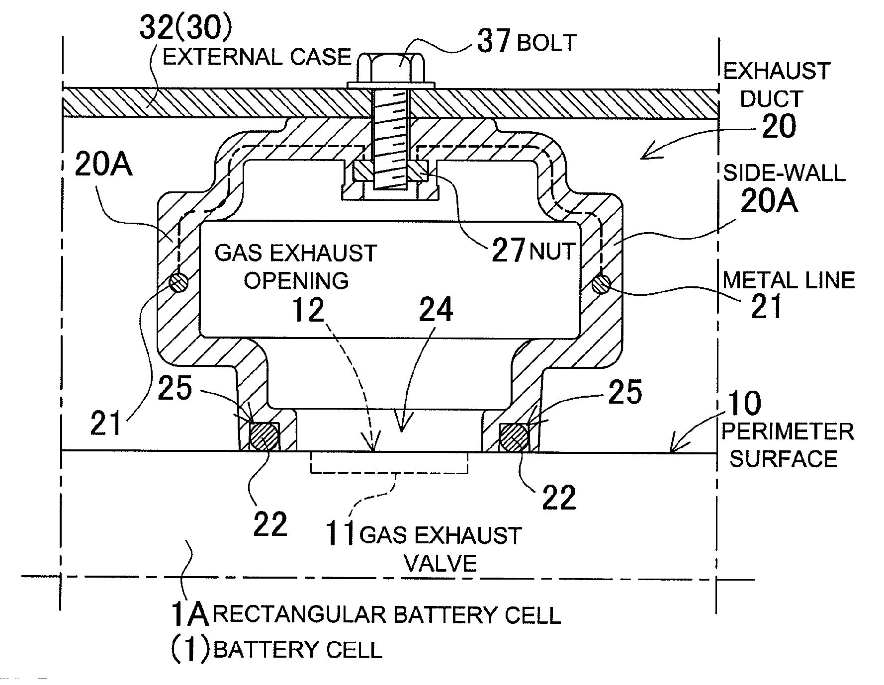
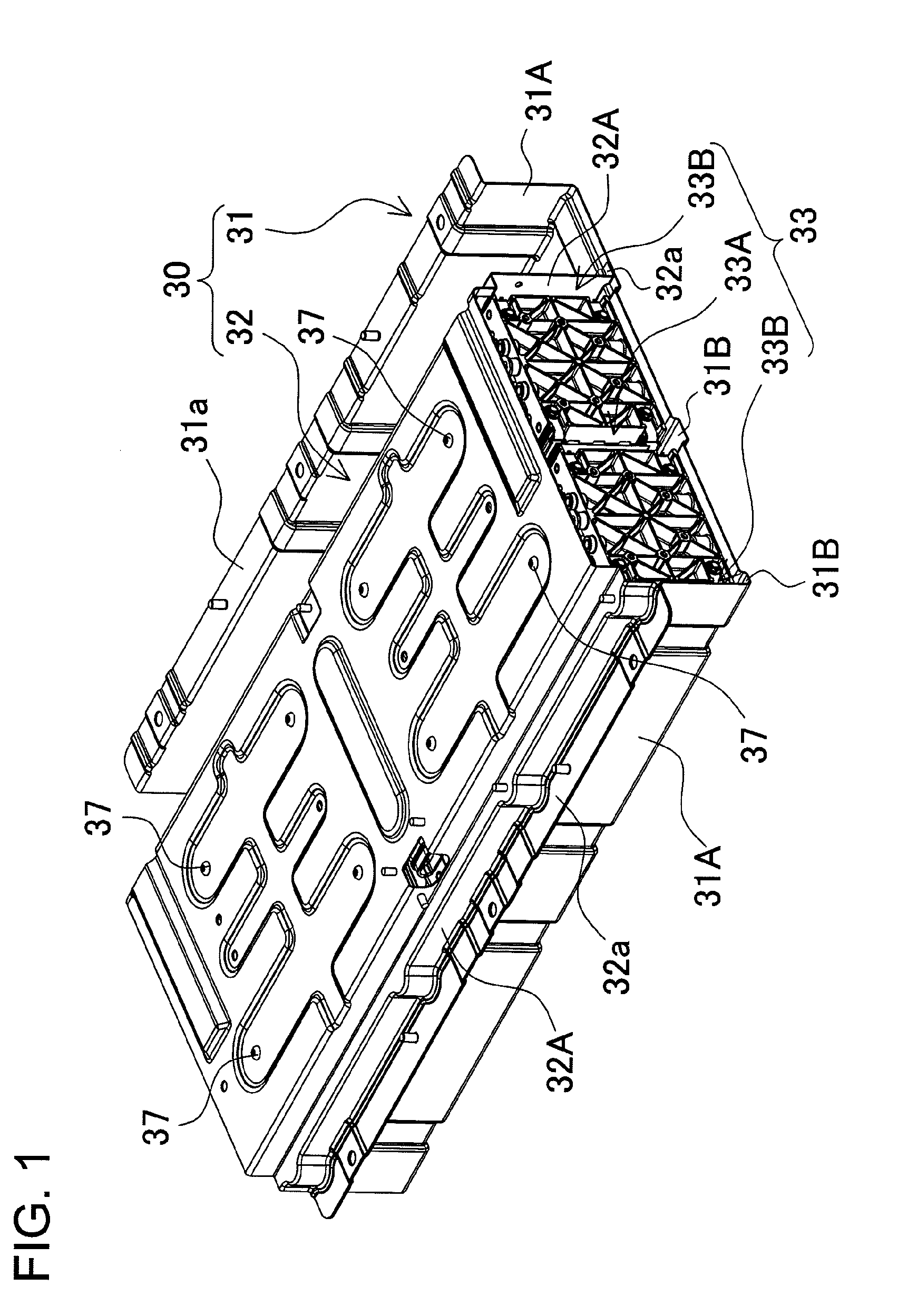
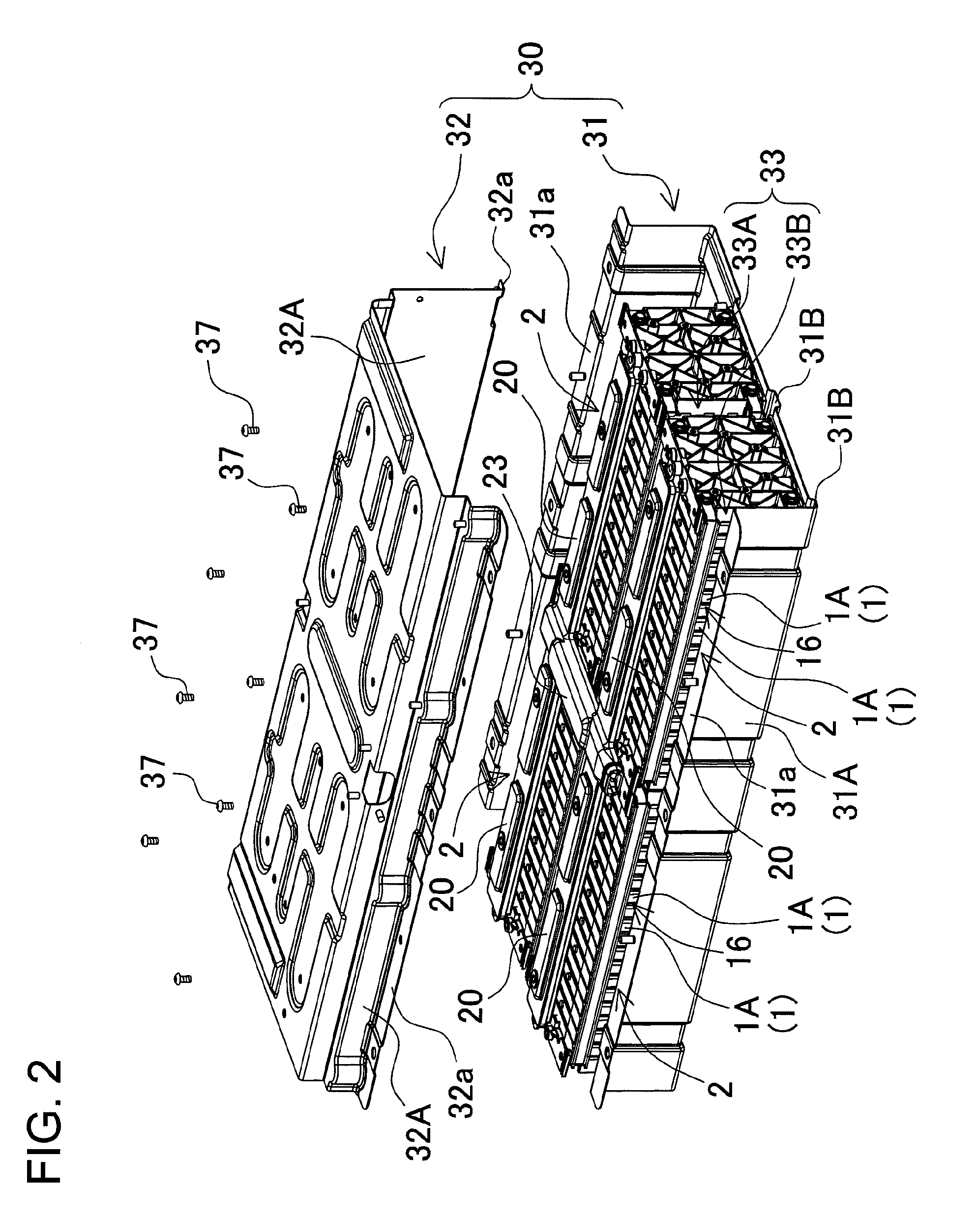
[0030]The battery system of FIGS. 1 and 2 is provided with battery blocks 2 that connect a plurality of battery cells 1 having gas exhaust valves 11; and with hollow exhaust ducts 20 that connect to the gas exhaust valve 11 gas exhaust opening 12 of each battery cell 1 that makes up the battery blocks 2, and exhaust gas discharged from the gas exhaust openings 12 to the outside. In the figures, battery blocks 2 with exhaust ducts 20 attached to their upper surfaces are housed in an external case 30.

[0031]The battery bloc...


PUM


Abstract

The battery system is provided with battery blocks 2 that connect a plurality of battery cells 1 having gas exhaust valves 11; and with hollow exhaust ducts 20 that connect to the gas exhaust valve 11 gas exhaust opening 12 of each battery cell 1 that makes up the battery blocks 2, and that exhaust gas discharged from the gas exhaust openings 12 to the outside. The exhaust ducts 20 are made of plastic with embedded metal lines 21 that extend in the lengthwise direction.

Description

BACKGROUND OF THE INVENTION[0001]1. Field of the Invention[0002]The present invention relates to a battery system used primarily as a car power source to supply electric power to a motor that drives a vehicle such as a hybrid car or electric automobile, and in particular relates to a battery system that discharges gas from battery cell gas exhaust valves to the outside through exhaust ducts.[0003]2. Description of the Related Art[0004]In a battery system provided with many battery cells, high output voltage can be attained by connecting the battery cells in series. This battery system can be used in an application, such as a hybrid car power source apparatus, that charges and discharges batteries with high currents. In this battery system, batteries are discharged with extremely large currents during vehicle acceleration, and are charged with correspondingly high currents under conditions such as regenerative braking. To insure safe operation, battery cells are provided with gas exh...

Claims


Application Information

Patent Timeline
IPC IPC(8): H01M2/12H01M10/60H01M10/613H01M10/617H01M10/625H01M10/647H01M10/6557H01M10/6563H01M10/658H01M50/209
CPCH01M2/1077H01M2/1205H01M10/0525Y02T10/7011H01M10/5016H01M10/5032H01M10/5059H01M10/5004H01M10/625H01M10/647H01M10/6557H01M10/613Y02E60/10H01M50/308H01M50/209
Inventor OKADA, WATARU
Owner SANYO ELECTRIC CO LTD
Why Eureka
Try Eureka