Control apparatus and control method

a control apparatus and control method technology, applied in the direction of instruments, coding, code conversion, etc., can solve the problems of failure detection using software, and achieve the effects of preventing the continuation of processing, preventing the error of bit, and improving the safety

Active Publication Date: 2010-07-08
HITACHI LTD +1
View PDF27 Cites 10 Cited by
  • Summary
  • Abstract
  • Description
  • Claims
  • Application Information

AI Technical Summary

Benefits of technology

[0020]When a failure is detected by either the first code generation part or the second code generation part, the first code generation part and the second code generation part prevents the first stored information from being input to the first processor and the second processor, respectively. If a bit error is caused by a failure in each processor or each bus interface during reading, therefore, the present invention makes it possible to prevent the bit error from being detected falsely and prevent the first stored information from being input to the first processor and the second processor.
[0021]According to the present invention, a failure which has occurred in each processor or each bus interface can be detected certainly. If a failure is detected at the time of writing, writing information into the main memory is inhibited. If a failure is detected at the time of reading, inputting information to each processor is inhibited. In other words, it is possible to detect a failure immediately and certainly and prevent continuation of processing in the unstable state. As a result, the safety is further improved.

Problems solved by technology

If a failure occurs in a memory interface ranging from an output of the unit for conducting comparison between micro-processors to a main memory, however, failure detection using software must be conducted because there is no detection units using hardware.
During real operation time between nth diagnostic processing and (n+1)st diagnostic processing, however, there is a possibility that operation will be continued while remaining in the unstable state because an abnormality cannot be detected, resulting in a problem.

Method used


Image

  • Control apparatus and control method
  • Control apparatus and control method
  • Control apparatus and control method

Examples


Embodiment Construction

[0032]Hereafter, embodiments of the present invention will be described in the following order. The embodiments are provided with various restrictions which are technically desirable. However, the scope of the present invention is not restricted to those embodiments unless it is especially stated in the ensuing description that a requirement restricts the present invention. For example, numerical value conditions of respective parameters mentioned in the ensuing description are merely preferred examples. Dimensions, shapes and arrangement relations in the drawings used in the description are also schematic.

1. One Embodiment

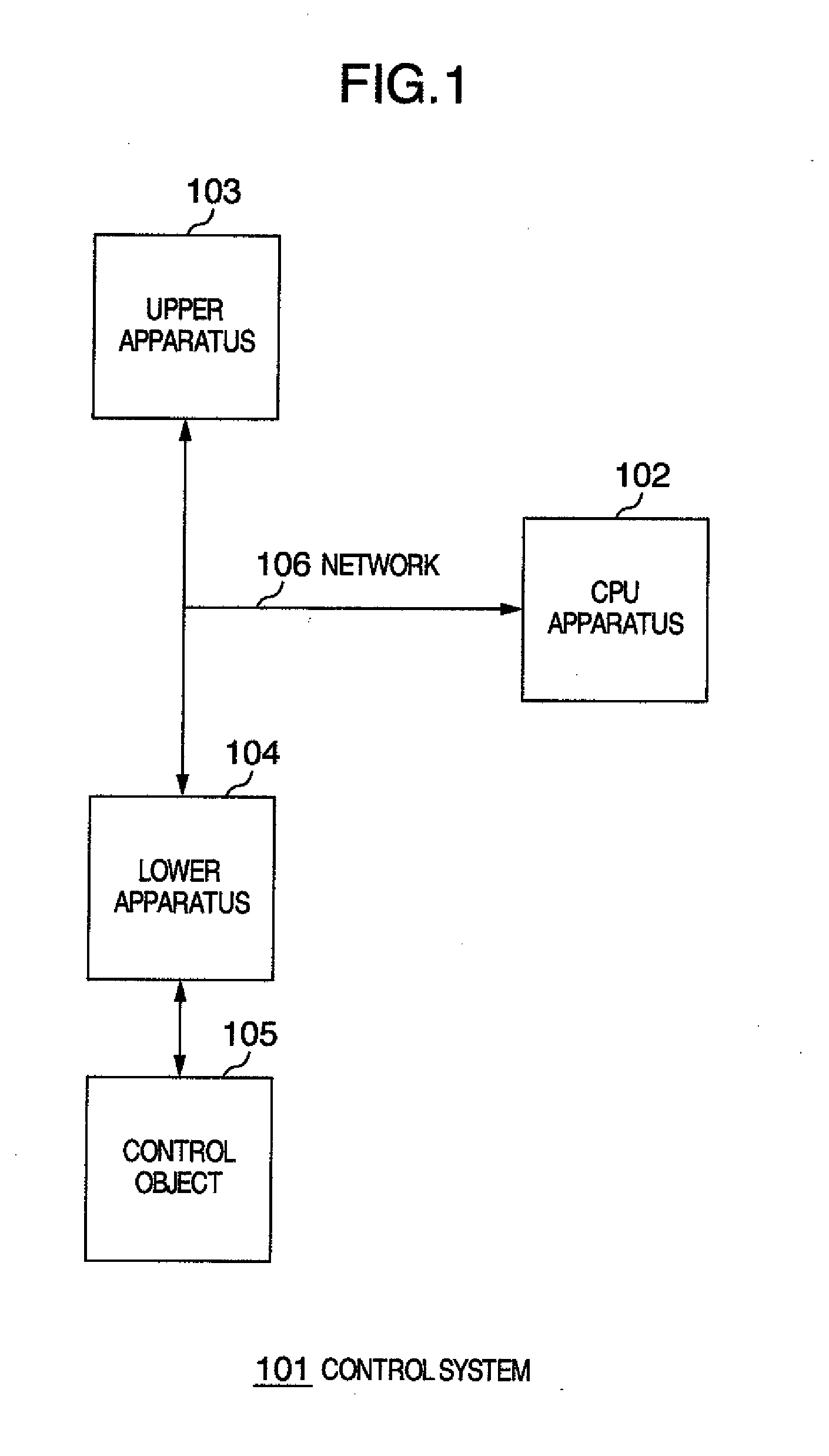
[0033](1) Configuration of control system

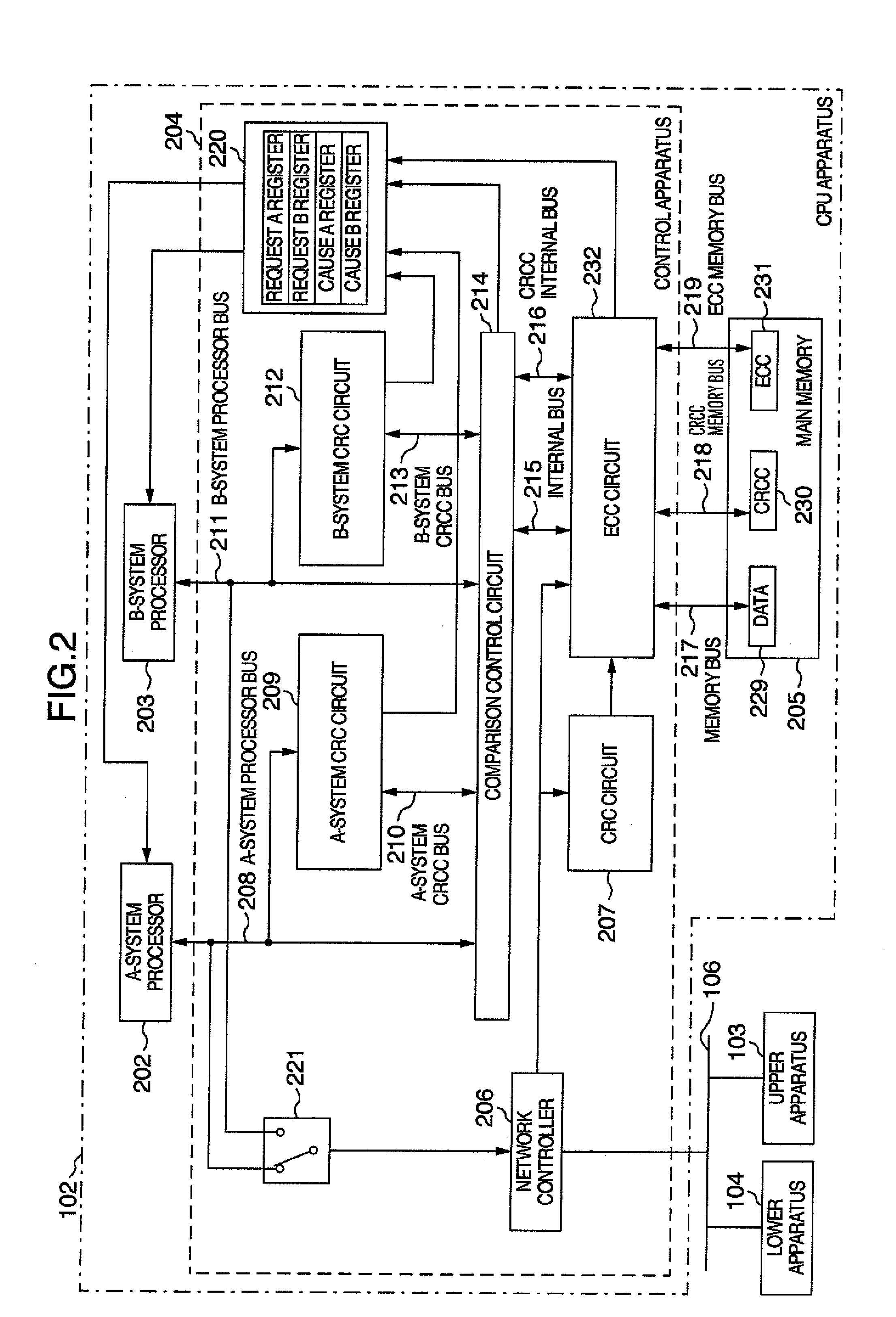
[0034](2) Configuration of CPU apparatus

[0035](3) Configuration of A-system CRC circuit

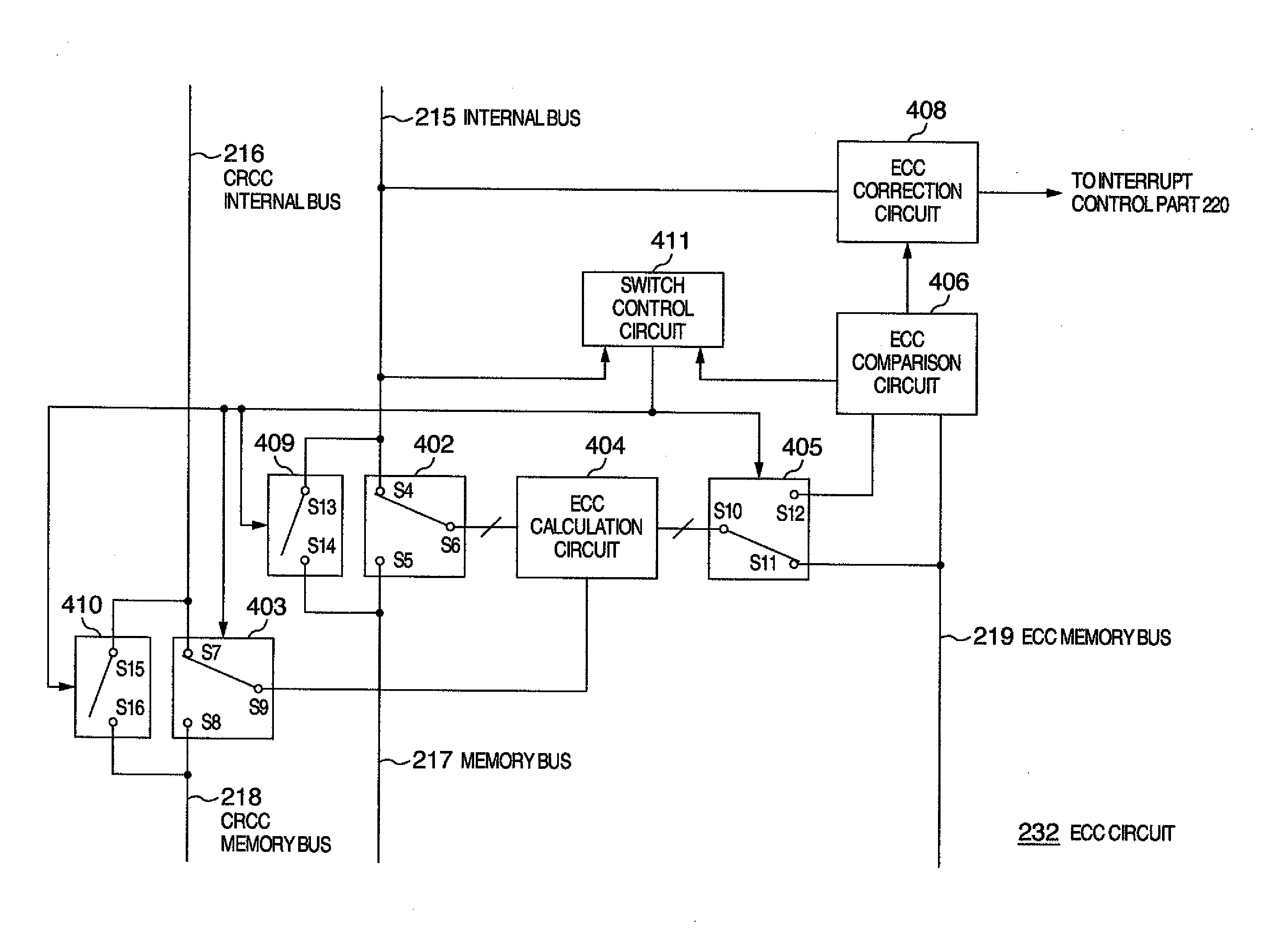
[0036](4) Configuration of ECC circuit

[0037](5) Mode transition in CPU apparatus

[0038](6) Operation of CPU apparatus

[0039](7) Failure detection range in CPU apparatus

1. One Embodiment

Configuration of Control System

[0040]Hereafter, an embo...


PUM


Abstract

A failure is detected immediately and certainly, and continuation of processing in an unstable state is prevented. A first error detection code is generated from first information which is output as a result of execution of a predetermined program conducted by a first processor. A second error detection code is generated from second information which is output as a result of execution of the program conducted by a second processor which is configured so as to output the same computation result as that of the first processor. It is detected whether the first information is the same as the second information, and it is detected whether the first error detection code is the same as the second error detection code. Writing the first information or the second information into a main memory is controlled on the basis of a result of the detection.

Description

INCORPORATION BY REFERENCE[0001]The present application claims priority from Japanese applications JP2009-001899 filed on Jan. 7, 2009, the content of which is hereby incorporated by reference into this application.BACKGROUND OF THE INVENTION[0002]The present invention relates to a control apparatus provided in a programmable electronic apparatus and a control method for the electronic apparatus.[0003]In process facilities such as atomic power plants and chemical plants which are potentially very dangerous, a passive countermeasure using protection facilities such as barriers and an active countermeasure using a safety apparatus such as an emergency stop apparatus are taken in order to reduce influences upon workers and the peripheral environment in an emergent situation. Among them, control of the safety apparatus is conventionally implemented by electromagnetic and mechanical means such as relays.[0004]As techniques in programmable control devices represented by programmable logic...

Claims


Application Information

Patent Timeline
Patent Type & Authority Applications(United States)
IPC IPC(8): H03M13/05G06F11/10
CPCH03M13/09G06F11/1008
Inventor FUNAKI, SATORUKIYOFUJI, YASUHIROSUENAGA, MASASHIKOKURA, SHINKOBAYASHI, EIJIONOZUKA, AKIHIROSEKI, YUSUKESHIMIZU, TOSHIKITAHARA, YUKIKOSUGIMOTO, YUTA
Owner HITACHI LTD
Why Eureka
Try Eureka