Hybrid Locomotive Regenerative Energy Storage System and Method

a technology of regenerative energy storage and hybrid locomotives, applied in braking systems, railway stations, roads, etc., can solve the problems of increasing the cost and size of battery packs, and increasing the weight of vehicles. cost and energy saving

Inactive Publication Date: 2010-07-15
ENVIRONMENTAL PROTECTION AGENCY US
View PDF27 Cites 33 Cited by
  • Summary
  • Abstract
  • Description
  • Claims
  • Application Information

AI Technical Summary

Benefits of technology

[0009]It is also an object of the invention to provide improved methods of operation to improve the cost-effectiveness for the reduction of fuel consumption in such vehicles.SUMMARY OF THE INVENTION
[0011]In a more preferred embodiment, braking may be performed directly by a hydraulic energy storage system simultaneously with electric dynamic braking on a train. A portion of electrical power generated in dynamic braking may be stored in a battery. Braking may also be performed hydraulically, through using a portion of the kinetic energy of the train to drive one or more hydraulic pump / motors as pumps to pressurize fluid for storage in one or more high pressure accumulators on board the train. The pressurized fluid may then be used to drive the pump / motor(s) to help propel the train.
[0014]Great cost savings may be achieved with the present invention by enabling substitution of the energy storage cars or locomotives of the present invention for one or more of multiple locomotives used for freight train routes. This could be done on a route-by-route basis. The energy storage car could be sized to deliver comparable horsepower to the omitted locomotive when needed. The savings gained in not needing a locomotive, and / or being able to redeploy the locomotive for other use, is significant.

Problems solved by technology

Two principal drawbacks for hybrid electric powertrains for heavy vehicles are that the storage batteries for such powertrains are expensive, and that current batteries which are not completely cost-prohibitive are severely limited in their ability to quickly capture and store large bursts of energy such as may occur in attempted regenerative braking of a heavy or fast-moving vehicle.
As a result, with state of the art hybrid electric technology, a typical hybrid electric passenger car is able to recover and re-use on average only about one-third or less of its kinetic energy lost in braking, a typical prototype heavy-duty hybrid electric truck or bus can recover and re-use only about 15-20% of its kinetic energy lost in braking, and an extremely heavy vehicle such as a hybrid electric locomotive with freight would be expected to recover and re-use only a very small percentage of its kinetic energy in braking The cost and size of the battery pack needed also greatly increases with the increase in vehicle weight and energy to store.
In addition, the ability to significantly buffer engine operation (i.e., maintain engine operation at good efficiency levels through use of the secondary power system to add or subtract power to the engine output to meet vehicle demand) is limited for hybrid electric powertrains where the engine is large (again because of the limited efficient charge / discharge rates for batteries which reduce efficiency and durability when charging or discharging at high power levels), such as in heavy vehicles, trains or locomotives.

Method used


Image

  • Hybrid Locomotive Regenerative Energy Storage System and Method
  • Hybrid Locomotive Regenerative Energy Storage System and Method
  • Hybrid Locomotive Regenerative Energy Storage System and Method

Examples


Embodiment Construction

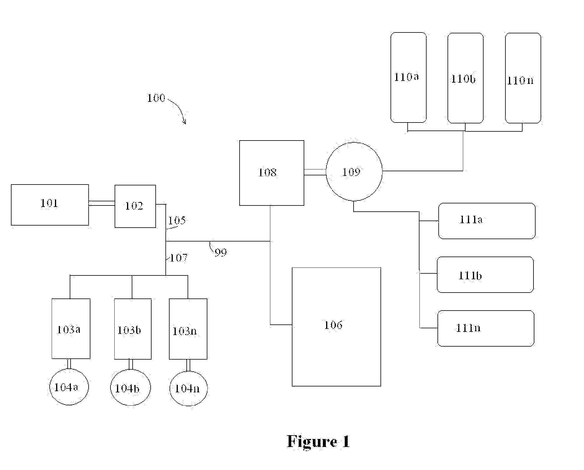
[0022]FIG. 1 is a schematic diagram of a powertrain of the present invention for use in conjunction with a diesel-electric locomotive. For simplicity sake in presenting each of the figures herein, common elements such as switches, inverters, and valves are not shown, but will be understood to exist as needed for the system to operate. These elements are well-known and easily incorporated by those with skill in the art(s).

[0023]Referring to FIG. 1, in diesel-electric locomotive 100, an internal combustion engine 101 drives a main electric / motor generator 102 to provide electric current through lines 105 and 107 to drive multiple electric motor / generators 103a, 103b . . . to 103n, as motors to drive wheels 104a, 104b . . . to 104n of the locomotive. Any actual number of motors and / or wheels may be used. Propulsion of the locomotive is performed as a known diesel-electric locomotive.

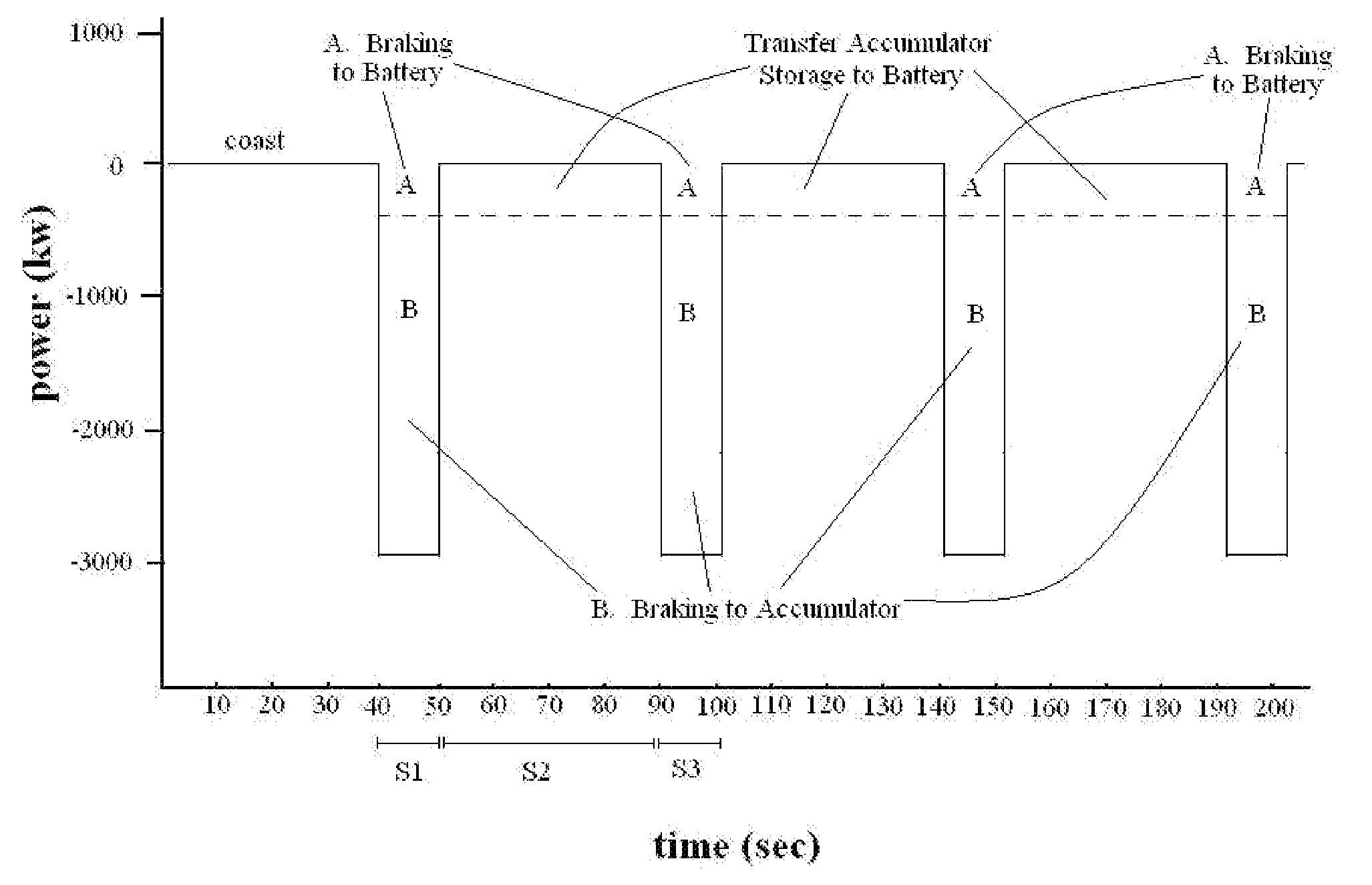
[0024]In dynamic braking, electrical power generated by the traction motors 103a-n is routed to another ...


PUM


Abstract

An energy storage car for a locomotive includes a hydraulic energy storage system designed to capture and reuse energy normally lost in dynamic braking The energy storage car is preferably configured to provide functions sufficient to replace one of multiple locomotives used to pull a freight train. Braking and other methods for improved efficiency of such trains are provided.

Description

CROSS-REFERENCE TO RELATED APPLICATIONS[0001]This application is a continuation-in-part of U.S. application Ser. No. 11 / 807,405, filed May 29, 2007, with priority to provisional application 60 / 849,286, filed Oct. 4, 2006.FIELD OF THE INVENTION[0002]The present invention relates to regenerative energy storage systems, particularly to those adapted for use with hybrid trains or locomotives.DESCRIPTION OF THE RELATED ART[0003]Hybrid powertrains have been investigated as a means to reduce fuel consumption and reduce harmful emissions in motor vehicles, including trains. Hybrid electric powertrains are the most commonly investigated hybrid vehicle powertrain. Hybrid electric powertrains have been found capable of reducing fuel consumption and harmful emissions in some applications, with certain drawbacks.[0004]Two principal drawbacks for hybrid electric powertrains for heavy vehicles are that the storage batteries for such powertrains are expensive, and that current batteries which are n...

Claims


Application Information

Patent Timeline
Patent Type & Authority Applications(United States)
IPC IPC(8): B61C7/04B61C9/14B61B1/00B61C7/02
CPCB60T1/10Y02T30/10B61C7/00Y02T30/00
Inventor READ, DAVID H.
Owner ENVIRONMENTAL PROTECTION AGENCY US
Why Eureka
Try Eureka