Catalyzed hot gas heating system for concentrated solar power generation systems

a technology of solar power generation and concentrated solar energy, applied in the field of thermal energy collection systems, can solve the problems of increasing the total cost of power production, electrical trace heating can be prone to failure, and the cost of electrical trace heating can be relatively high

Inactive Publication Date: 2010-07-15
SOLARRESERVE TECH
View PDF78 Cites 47 Cited by
  • Summary
  • Abstract
  • Description
  • Claims
  • Application Information

AI Technical Summary

Problems solved by technology

Electrical trace heating can, however, be relatively expensive, increasing total cost of power production.
Moreover, electrical

Method used


Image

  • Catalyzed hot gas heating system for concentrated solar power generation systems
  • Catalyzed hot gas heating system for concentrated solar power generation systems
  • Catalyzed hot gas heating system for concentrated solar power generation systems

Examples


Embodiment Construction

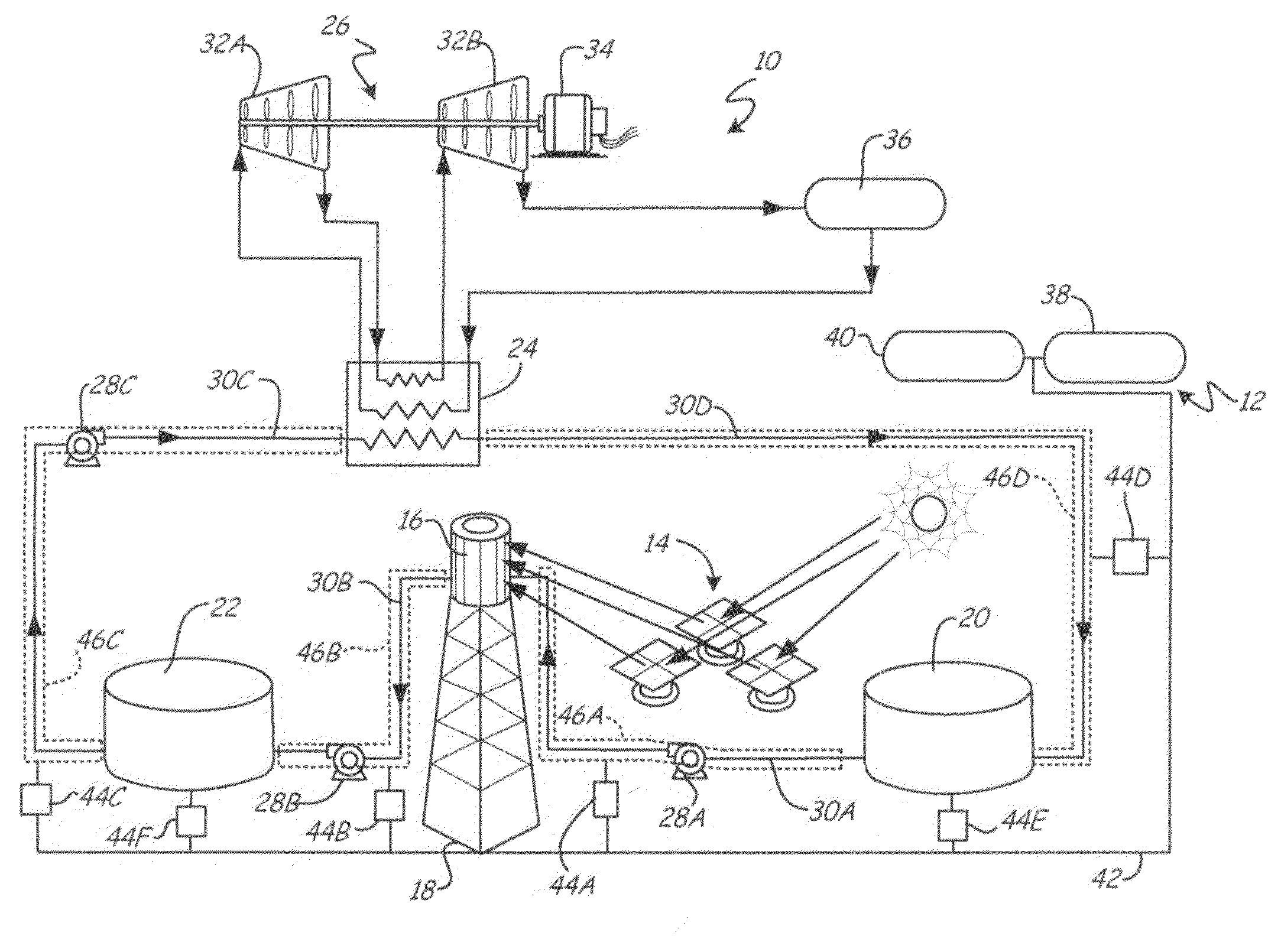
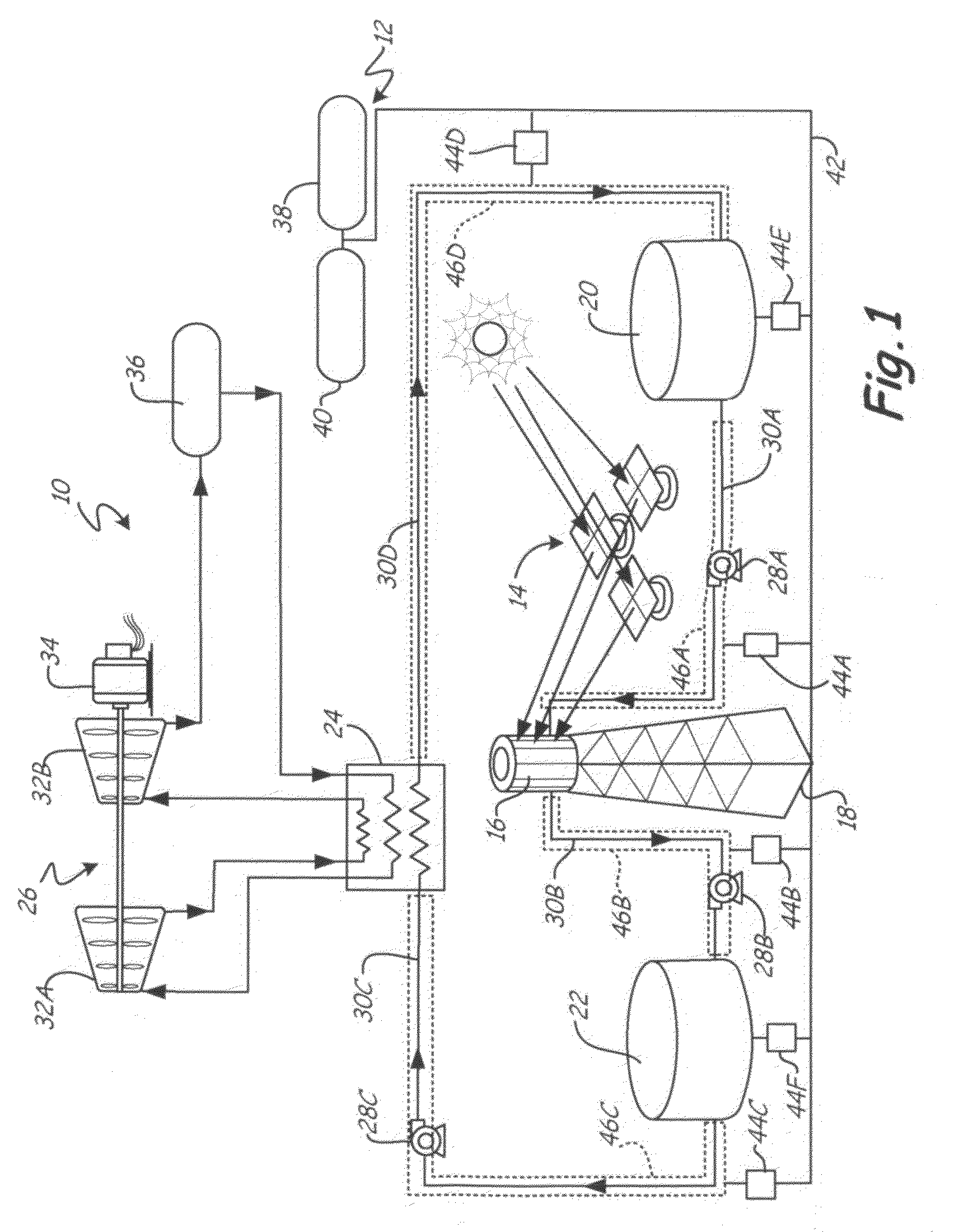
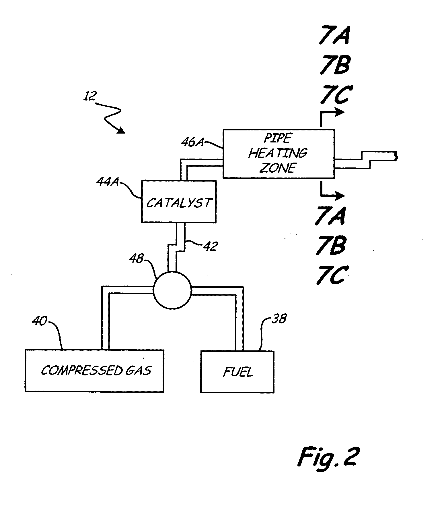
[0016]In general, the present invention includes a heating system for heating a heat transfer medium in a concentrated solar power generation system. The heating system includes catalysts positioned near various parts of the solar power generation system that can contain the heat transfer medium. A blend of fuel and air is blown across the catalysts, reacts, and creates heat which is then transferred to the various parts and ultimately to the heat transfer medium.

[0017]FIG. 1 shows a schematic diagram of concentrated solar power generation system 10 having heating system 12 of the present invention. In the embodiment shown, power generation system 10 comprises a power tower system having solar collector system 14, central receiver 16, tower 18, cold storage tank 20, hot storage tank 22, heat exchanger 24, generator 26, pumps 28A, 28B and 28C, and pipes 30A, 30B, 30C and 30D. In other embodiments, power generation system 10 may comprise a beam down solar power generation system or a ...


PUM


Abstract

A solar power generation system includes a fluid housing, a solar collector, and a heating system. The fluid housing contains a heat transfer medium. The solar collector concentrates solar energy onto the heat transfer medium. The heating system includes at least one gas tank containing a gas and fluidically connected to a first catalyst. The first catalyst is configured to catalyze gas from the gas tank to create hot gas. The heating system also includes a first hot gas pipe fluidically connected to the first catalyst and positioned with respect to the fluid housing such that hot gas flowing through the first hot gas pipe comes into thermal contact with the heat transfer medium within the fluid housing.

Description

CROSS-REFERENCE TO RELATED APPLICATION[0001]The present application is related to the following co-pending application filed on the same day as this application: “CATALYZED HOT GAS HEATING SYSTEM FOR PIPES” by inventors A. Little and A. Zillmer (U.S. patent application Ser. No. ______ Attorney Docket No. PA-9579-US / U74.12-100).BACKGROUND[0002]The present invention relates to thermal energy collecting systems, and in particular, to heating a molten storage medium used in thermal energy collecting systems.[0003]Throughout the world there is an increasing demand for energy, which is typically provided by fossil fuels such as petroleum and coal. Additionally, due to scarcity and adverse environmental effects of fossil fuels, cleaner, renewable energy sources are becoming more desirable. As technology advances, alternative fuel sources are becoming practical to replace, or at least augment, conventional power plants to meet worldwide energy demand in a clean manner. In particular, solar ...

Claims


Application Information

Patent Timeline
IPC IPC(8): F24J2/46F24J2/04F03G6/00F24S90/00
CPCF16L9/18F16L9/19F16L53/002Y02E10/46F24J2/07F24J2/42F24J2/4649F16L59/143F16L53/32F24S20/20F24S80/20F24S90/00F28D2020/0047
Inventor ZILLMER, ANDREW J.LITTLE, ALFRED
Owner SOLARRESERVE TECH
Why Eureka
Try Eureka