Optical system and display

a technology of optical system and display, applied in the field of optical system, can solve the problems of reducing the aesthetics of such displays, and producing images that do not appear flat, and achieve the effect of low cos

Inactive Publication Date: 2010-07-15
SHARP KK
View PDF25 Cites 171 Cited by
  • Summary
  • Abstract
  • Description
  • Claims
  • Application Information

AI Technical Summary

Benefits of technology

[0044]It is thus possible to provide an arrangement which allows a non-flat image to be created in a relatively simple way. For example, a conventional or unmodified display device may be used and the flat or substantially flat image produced by such a device can be converted into a non-flat image, fo

Problems solved by technology

However, such displays are generally aesthetically limited because of their inability to produce images that differ from the standard two dimensional (2D) images displayed in the plane of the display.
In addition to reducing the aesthetics of such displays, the inability to produce images that do not appear flat may provide limited realism of such displays.
Although stereoscopic and autostereoscopic displays are known and can produce an impression of a three-dimensional image, such displays may produce eye strain and headache problems because of a potential limited freedom of viewing position and focussing issues.
Although such displays become more and more common, they generally do not feature any aesthetically appealing features, aside from their large size, that would make them stand out of the ordinary and facilitate their acceptance.
However, this device produces a stereo image pair to generate 3D images rather than images with curved-appearance.
Drawbacks of auto-stereoscopic displays include limited head f

Method used


Image

  • Optical system and display
  • Optical system and display
  • Optical system and display

Examples


first embodiment

[0105]In the first embodiment and all following embodiments based on a similar configuration, details and configuration of the display system may be varied in a number of ways so as to optimise the performance for different applications.

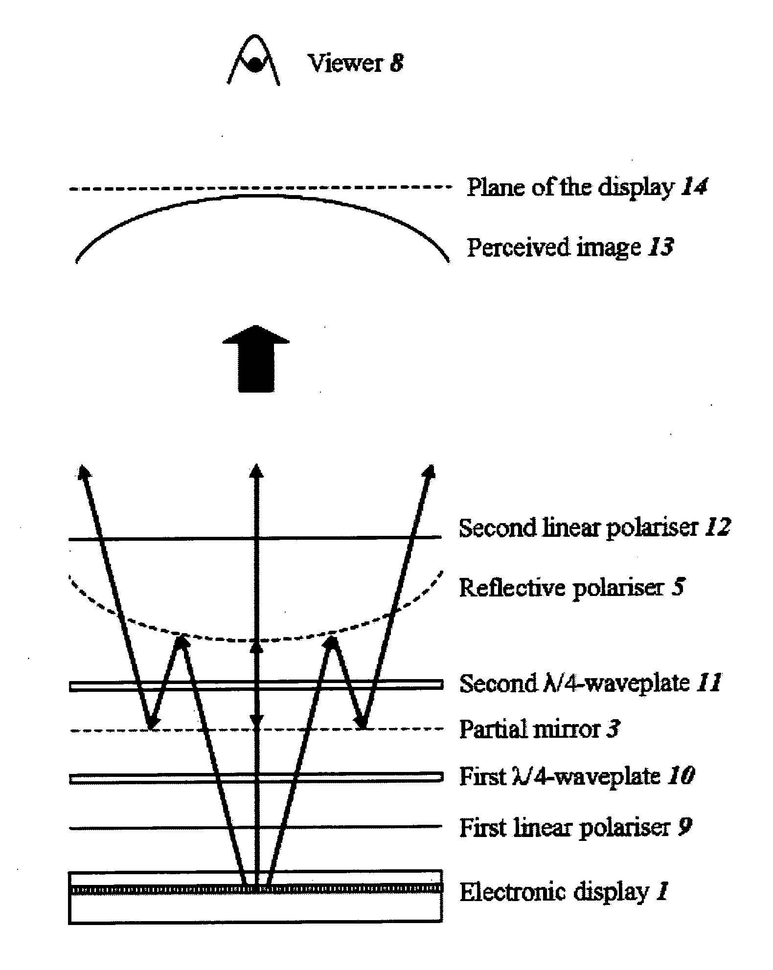
[0106]For example, as described above, the partial mirror 3 reflects approximately 50% of light incident upon it and transmits approximately 50%. This leads to the final curved image 13 (shown in FIG. 7) seen by the viewer 8 having a brightness which is approximately one-quarter of its original brightness as displayed by the electronic display 1. Although this brightness value of one-quarter is the highest achievable with the system configuration of this embodiment, it will be appreciated that, for further embodiments of this invention, the optical properties of the partial mirror 3, for instance the reflectivity / transmissivity ratio, may be varied to select the relative brightness of the displayed image. In other words, the partial mirror 3 is desig...

second embodiment

[0122]the invention is shown in FIGS. 14a and 14b. This embodiment provides the capability of optionally utilizing the electronic display 1 as a standard 2D display or as a curved display. For example, such a capability may be of benefit for large-area advertising displays, which may operate like common conventional displays in the 2D mode when displaying text information or common banners but which may take advantage of an enhanced aesthetic appearance by switching to the “curved mode” when trying to catch the attention of viewers for a particular advertising video.

[0123]As illustrated in FIGS. 14a and 14b, the system uses the same components as described in the first embodiment. In addition, a switchable half-wave (“switchable λ / 2”) plate 21 is disposed between the input linear polariser 9 and the first quarter-wave plate 10. Such a switchable half-wave plate 21 may comprise a liquid crystal cell which is capable of being switched on and off electrically. When switched on, the pla...

third embodiment

[0137]the invention is illustrated in FIGS. 15a and 15b. The only element in this embodiment which is not also described in the previous embodiments is a cholesteric reflector 22. This is a liquid-crystal layer with a natural helical structure which causes it to reflect one circular polarisation state while transmitting the other. Such reflectors are well-known and are disclosed in standard books on liquid crystal technology, for example the book by Lueder mentioned previously. Such reflectors may be made so that they may be switched off by the application of an applied electric field, or may simply be fixed and unswitchable. If they are left unswitched, then the liquid crystal layer may be fixed in place by polymerisation of the liquid crystal molecules themselves or by polymerisation of an accompanying monomer.

[0138]In the display shown in FIGS. 15a and 15b, the first partial reflector comprises a partial mirror 3 whereas the second partial reflector comprises a fixed cholesteric ...


PUM


Abstract

An optical system is provided, for example for use with a display device (1) to convert a flat image from the display device (1) to a non-flat image. The optical system comprises first and second spaced-apart partial reflectors (3, 5), at least one of which is non-flat. The reflectors (3, 5), together with polarisation optics (2, 4), provide a light path (6) such that light from the display (1) is at least partially transmitted by the first reflector (3), partially reflected by the second reflector (5), partially reflected by the first reflector (3) and partially transmitted by the second reflector (5) so that a viewer (8) perceives a non-flat, for example curved, image. Light which does not follow the light path (6) is prevented from leaving the optical system.

Description

TECHNICAL FIELD[0001]The present invention relates to an optical system for converting a flat image to a non-flat image. The present invention also relates to a display for producing a non-flat image. Such a display may be used, for example, to provide a curved appearance to the displayed image. Such a display may, for example, be used in information display applications including automotive (for example as an instrument display), advertising, television, games or other amusement applications, immersive display applications and in any applications where enhanced aesthetics may be desirable to the user.BACKGROUND ART[0002]It is known for vehicles, such as automobiles and aircraft, to include an electronic display providing an image of, for example, an instrument cluster for replacing discrete mechanical or electrical dials. However, such displays are generally aesthetically limited because of their inability to produce images that differ from the standard two dimensional (2D) images ...

Claims


Application Information

Patent Timeline
IPC IPC(8): G09G5/02G02B27/10G02B27/28G02B27/12G02F1/13G06F3/041
CPCG02B3/005G02B27/2214G02B3/0056G02B30/27G02F1/1335G02B30/40
Inventor GAY, GREGORYWALTON, HARRY GARTH
Owner SHARP KK
Why Eureka
Try Eureka