DC bus clamp circuit to prevent over voltage failure of adjustable speed drives

a technology of adjustable speed and clamp circuit, which is applied in the direction of emergency protective arrangements for limiting excess voltage/current, arrangements responsive to excess voltage, electric motor control, etc., can solve the problems of shortened life of drive components, negative side effects, and high frequency electrical transients, and achieves lower power ratings

Active Publication Date: 2010-07-15
ROCKWELL AUTOMATION TECH
View PDF17 Cites 24 Cited by
  • Summary
  • Abstract
  • Description
  • Claims
  • Application Information

AI Technical Summary

Benefits of technology

[0008]The present inventors have identified a protective circuit that may be used to provide over voltage protection for an ASD. The protective circuit provides the benefits of fewer components with lower power ratings than existing protective circuits. The protective circuit may be incorporated directly in the ASD for continuous protection or mounted externally and connected to the ASD under operating conditions that require the circuit. This flexibility for mounting the protective circuit allows the capacitor of the protective circuit to be sized either in relation to capacitive elements on the DC bus within the ASD or according to external capacitance observed at the output of the ASD. In addition, the circuit is only operative during an overvoltage condition, allowing for power ratings lower than would be required for continuous operation.
[0009]Specifically then, the present invention applies to a power supply having a DC bus providing a DC voltage across a positive and negative bus rail. The DC bus is connected to one or more inverters which provide power to windings of an electric motor. The DC bus has at least one capacitive element connected across the positive and negative bus rails. The present invention is an apparatus for reducing electrical transients on the DC bus including at least one damping element having a resistor and a damping capacitor connected in parallel with the resistor. A first and a second diode are each connected in series with a damping element between the common point and the positive and negative bus rails, respectively. The direction of conductance of the first diode is from the common point to the positive rail, and the direction of conductance of the second diode is from the negative rail to the common point.
[0010]Thus, it is one object of the invention to provide a damping circuit to reduce electrical transients across the capacitive elements of a DC bus. The diode connected in series with the damping element acts as a switch to engage the damping circuit only when it is needed, allowing for lower power ratings on the damping circuit components.
[0015]The apparatus may be contained within the adjustable speed drive. Thus it is one object of the invention to provide inherent protection against certain fault and adverse operating conditions.

Problems solved by technology

While an ASD provides the benefit of speed control for a motor, it can also introduce negative side effects.
However, the high frequency voltage pulses also introduce high frequency electrical transients at the motor output.
This voltage stress may similarly result in a shortened life of the drive components.
If multiple motors are operating from a common DC bus, it is possible that a single motor may fail while the other motors continue operation.
It is also possible that a single motor may be damaged yet continue to operate.
For example, if one winding in a motor has a ground fault condition, it may draw substantial currents while that phase is switched on by the inverter and substantial voltage or current spikes can be generated.
Therefore, if a single motor fails, or begins to fail, it may affect other motors or drives on the common DC bus and cause subsequent motor or drive failures.
This approach may result in undesirable down time of a motor or even an entire process line on which the motor is installed.
The increased power ratings or number of components results in an increased cost of the circuit.

Method used


Image

  • DC bus clamp circuit to prevent over voltage failure of adjustable speed drives
  • DC bus clamp circuit to prevent over voltage failure of adjustable speed drives
  • DC bus clamp circuit to prevent over voltage failure of adjustable speed drives

Examples


Embodiment Construction

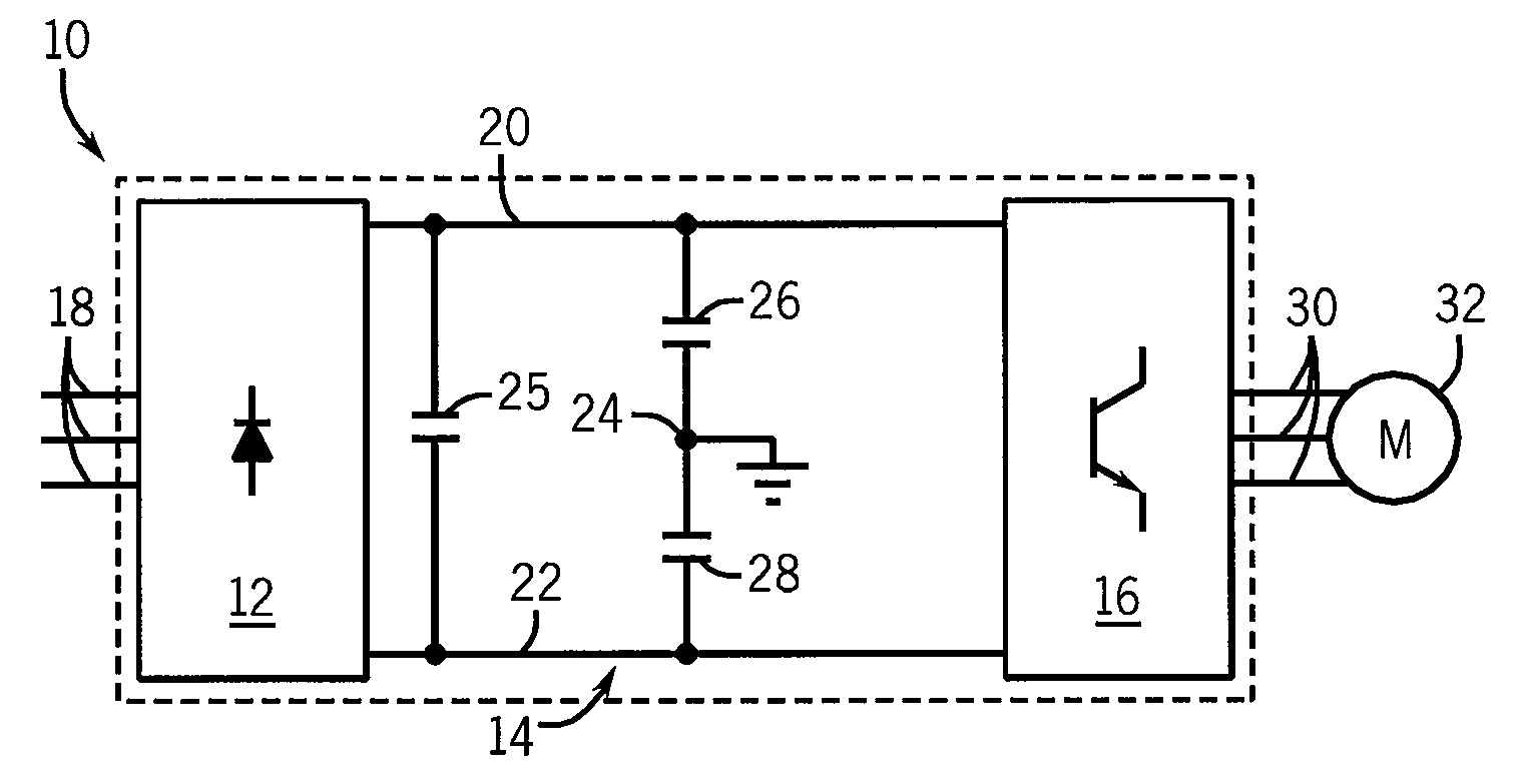
[0030]Referring to FIG. 1, a common topology for an Adjustable Speed Drive 10 is illustrated. The ASD 10 includes a rectifier section 12, a DC bus section 14, and an inverter section 16. The ASD 10 receives three-phase AC input voltage 18 into the rectifier section 12. The rectifier section 12 may include passive or active rectification, for example diodes, thyristors, silicon controlled rectifiers, or transistors as is known in the art, to convert the three-phase AC input voltages into DC voltages. These DC voltages are present on the positive and negative DC bus rails 20 and 22 of the DC bus section 14. Typical DC voltages may be a positive or negative 650 volts for a common 460 volt, three-phase AC input voltage. To maintain a stiff DC voltage on each of the positive and negative bus rails, 20 and 22, a DC bus capacitor 25 is included between the rails 20 and 22, wherein a stiff DC voltage remains approximately equal to the peak value of the AC input voltage 18 despite transient ...


PUM


Abstract

The present invention relates to a protective circuit to provide over voltage protection for an ASD. The protective circuit provides the benefits of fewer components with lower power ratings than existing protective circuits. The protective circuit may be incorporated directly in the ASD for continuous protection or mounted externally and connected to the ASD under operating conditions that require the circuit. This flexibility for mounting the protective circuit allows the capacitor of the protective circuit to be sized either in relation to capacitive elements on the DC bus within the ASD or according to external capacitance observed at the output of the ASD. In addition, the circuit is only operative during an overvoltage condition allowing for power ratings lower than would be required for continuous operation.

Description

BACKGROUND OF THE INVENTION[0001]The present invention relates generally to protective circuits for adjustable speed drives for AC electric motors, and in particular to a DC bus clamping circuit providing protection against component failure during an over voltage fault or adverse operating conditions.[0002]Common AC motors use three-phase electrical power connected to the stator windings of a motor to run the motor. Each stator winding is connected to a different conductor from a three-phase power source, in which each conductor delivers a different phase of the electrical power to the motor. The three-phase power source may be a direct connection to line power, but more commonly, the motor is connected to an adjustable speed motor drive (ASD). The ASD allows for speed control of the motor not available by connecting the motor directly to line power.[0003]As is known in the art, there are many electrical topologies for ASDs used to convert the fixed voltage and frequency from the l...

Claims


Application Information

Patent Timeline
Patent Type & Authority Applications(United States)
IPC IPC(8): H02H9/04
CPCH02M1/32H02P29/02H02P27/06
Inventor WEI, LIXIANGLIU, ZHIJUNSKIBINSKI, GARY L.
Owner ROCKWELL AUTOMATION TECH
Why Eureka
Try Eureka