Robotic Fenestration Device Having Impedance Measurement

a robotic fenestration and impedance measurement technology, which is applied in the direction of prosthesis, blood vessels, catheters, etc., can solve the problems of internal bleeding, potentially life-threatening conditions, thin blood vessel walls, etc., and achieve the effect of facilitating the fenestration of endoluminal grafts

Inactive Publication Date: 2010-07-15
MEDTRONIC VASCULAR INC
View PDF8 Cites 69 Cited by
  • Summary
  • Abstract
  • Description
  • Claims
  • Application Information

AI Technical Summary

Problems solved by technology

Aneurysms result from weak, thinned blood vessel walls that “balloon” or expand due to aging, disease and / or blood pressure in the vessel.
Consequently, aneurysmal vessels have a potential to rupture, causing internal bleeding and potentially life threatening conditions.
Unfortunately, not all patients diagnosed with aortic aneurysms are presently considered to be candidates for endovascular grafting.
This is largely due to the fact that the anatomy of branch vessels is variable amongst patients, and most of the endovascular grafting systems of the prior art are not designed for use in regions of the aorta from which branches extend.
The deployment of endovascular grafts within regions of the aorta from which branch arteries extend, present additional technical challenges because in those cases the endovascular graft must be designed, implanted, and maintained in a manner which does not impair the flow of blood into the branch arteries.
One challenge that exists in such a procedure is how to accurately position the fenestration of the main stent graft in relation to the branch vessel.
If the stent graft is deployed in a main vessel and the position of a fenestration ends up offset from the branch vessel which it is intended to feed, it may be difficult to deploy guidewires and catheters from the stent graft into the branch vessel to enable delivery and / or correct positioning of the branch vessel stent graft.
Poor positioning of a branch vessel stent graft may cause the branch graft to kinks to such an extent that blood flow will be restricted or will not occur therethrough.

Method used


Image

  • Robotic Fenestration Device Having Impedance Measurement
  • Robotic Fenestration Device Having Impedance Measurement
  • Robotic Fenestration Device Having Impedance Measurement

Examples


Embodiment Construction

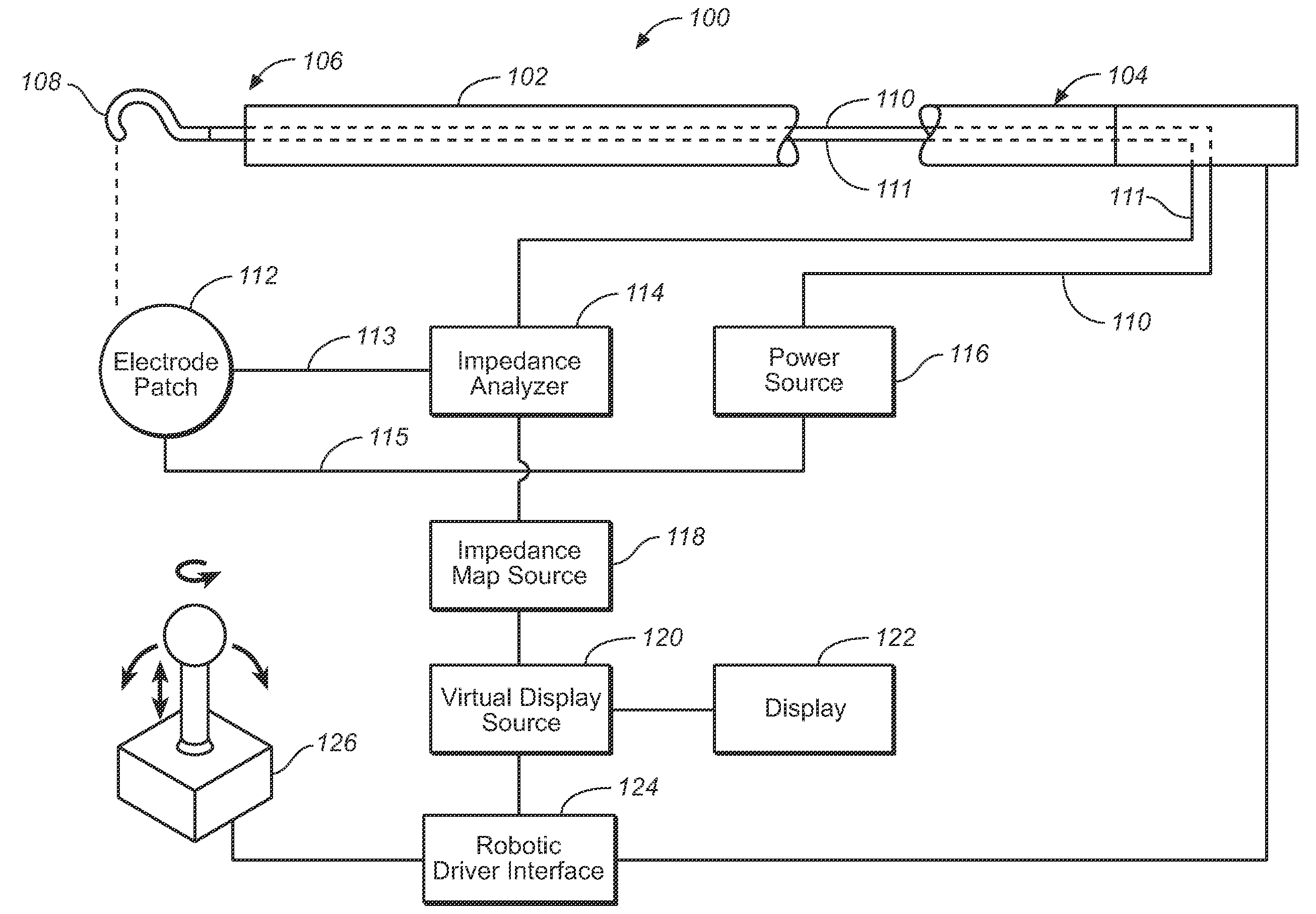
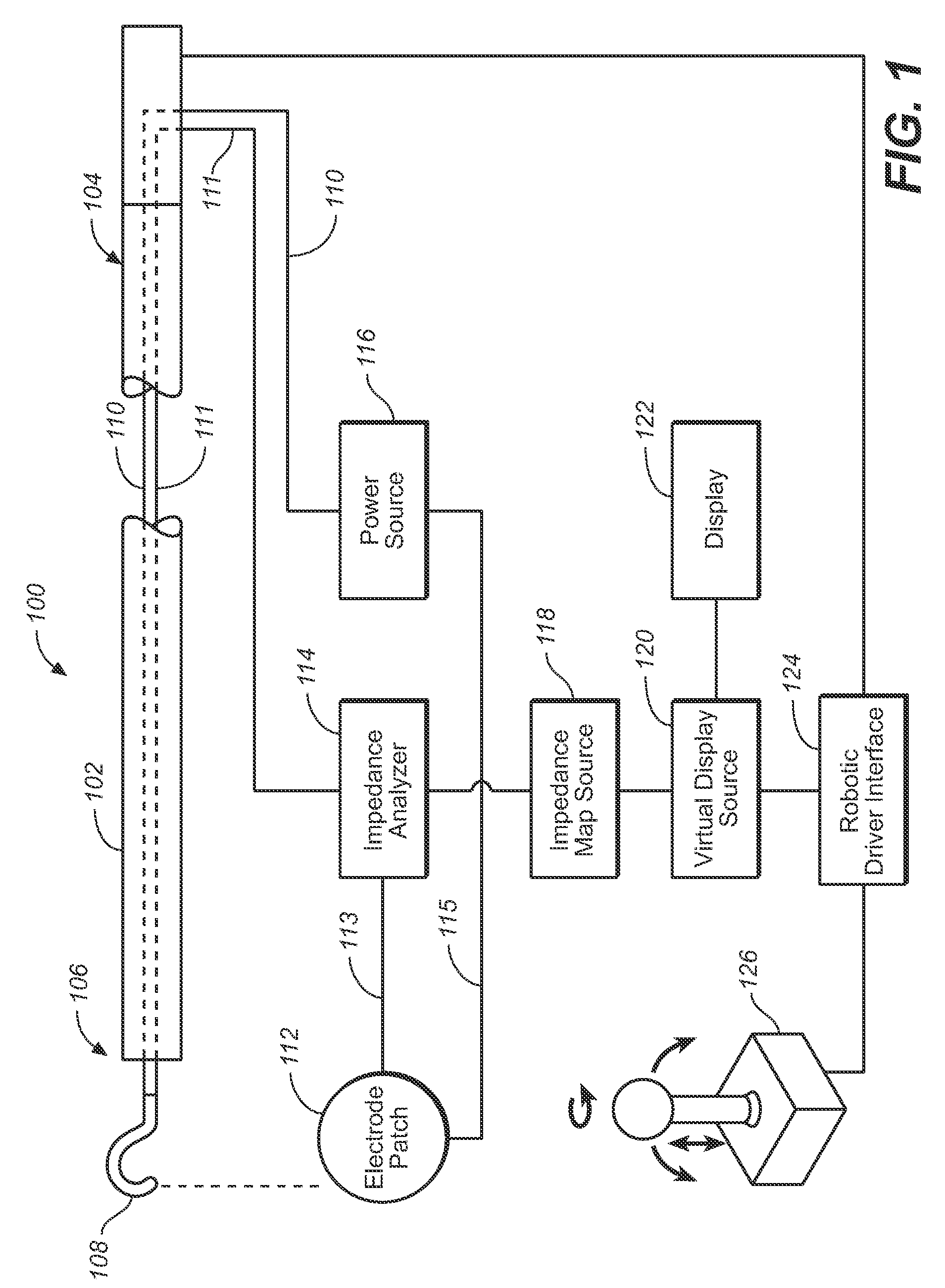
[0015]Specific embodiments are now described with reference to the figures, wherein like reference numbers indicate identical or functionally similar elements. When the terms “distal” and “proximal” are used in relation to a delivery system or a catheter system in the following description with respect to a position or direction relative to the treating clinician. “Distal” or “distally” are a position distant from or in a direction away from the clinician. “Proximal” and “proximally” are a position near or in a direction toward the clinician. However, when referring to the graft (whether in the delivery system or already implanted) the proximal end refers to the end of the graft material nearest the heart by way of blood flow path, while distal is the end farthest from the heart by way of blood flow path.

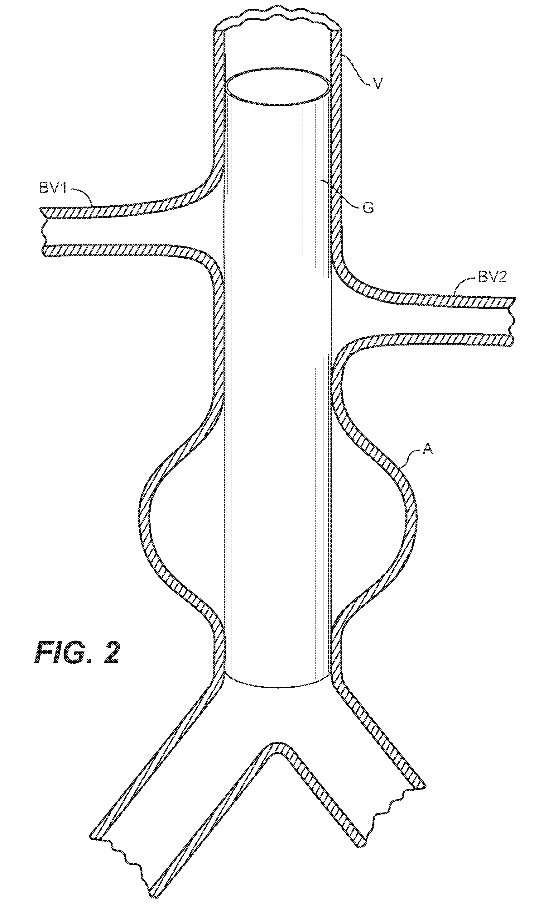
[0016]The following detailed description is merely exemplary in nature. Although the description herein is in the context of treatment of blood vessels such as the aortic, carotid, ...


PUM


Abstract

A method and system for real-time continuous impedance monitoring along the surface of a graft implanted within a main vessel to aid in optimally positioning an electrode at a branch vessel ostium. Due to the conductivity differences among various kinds of solid tissue and blood, a fenestration catheter system uses impedance monitoring as a tool to detect the location of branch ostia through graft cloth. Such information enables the fenestration electrode to be properly positioned for creation of a fenestration in the graft cloth in situ. In addition, the fenestration catheter system may utilize impedance information to avoid contact between the electrode and metal stent structures used to anchor the graft during an in situ fenestration procedure. The fenestration catheter system includes a catheter shaft, an electrode, one or more reference or indifferent electrodes, an impedance analyzer, a power source and an electrode position reference to record impedance measurements in relation to position.

Description

FIELD OF THE INVENTION[0001]The present invention relates generally to methods and systems for providing perfusion to branch vessels when a graft is implanted in a body lumen for the treatment of vascular disease.BACKGROUND[0002]Prostheses for implantation in blood vessels or other similar organs of the living body are, in general, well known in the medical art. For example, prosthetic vascular grafts constructed of biocompatible materials, such as Dacron or expanded porous polytetrafluoroethylene (ePTFE) tubing, have been employed to replace or bypass damaged or occluded natural blood vessels. In general, endovascular grafts typically include a graft anchoring component that operates to hold the tubular graft in its intended position within the blood vessel. Commonly, for grafts which are delivered using a minimally invasive approach (stent grafts) the graft anchoring component is one or more radially compressible stents that are radially expanded in situ to anchor the tubular graf...

Claims


Application Information

Patent Timeline
Patent Type & Authority Applications(United States)
IPC IPC(8): A61F2/84A61B5/053A61B19/00A61F2/06
CPCA61B5/0536A61B5/6855A61B18/1206A61B18/1492A61F2002/061A61B2019/2211A61B2562/02A61F2/07A61B2018/00875A61B2034/301
Inventor BRUSZEWSKI, WALTERMACHEK, JAMES
Owner MEDTRONIC VASCULAR INC
Why Eureka
Try Eureka