Plate-Frame Graphite-Foam Heat Exchanger

a heat exchanger and plate frame technology, applied in the field of energy conversion, can solve the problems of exacerbated drawbacks, unsuitable shell and tube heat exchangers, and generally characterized by relatively low heat transfer coefficients

Inactive Publication Date: 2010-07-22
LOCKHEED MARTIN CORP +1
View PDF23 Cites 30 Cited by
  • Summary
  • Abstract
  • Description
  • Claims
  • Application Information

AI Technical Summary

Benefits of technology

[0017]Each plate comprises a “sandwich” structure of a graphite-foam core that interposes a pair of barriers. The barriers are sub...

Problems solved by technology

Although shell and tube style heat exchangers are often used for ship/submarine service, they are typically characterized by relatively low heat transfer coefficients.
As a result, shell and tube heat exchangers are not well-suited for OTEC applications since they would require undesirably large surface areas.
This drawback is further exacerbated by the fact that there is normally only a small difference between seawater and process fluid temperatures.
Plate-frame heat exchangers have a high capital cost....

Method used


Image

  • Plate-Frame Graphite-Foam Heat Exchanger
  • Plate-Frame Graphite-Foam Heat Exchanger
  • Plate-Frame Graphite-Foam Heat Exchanger

Examples


Embodiment Construction

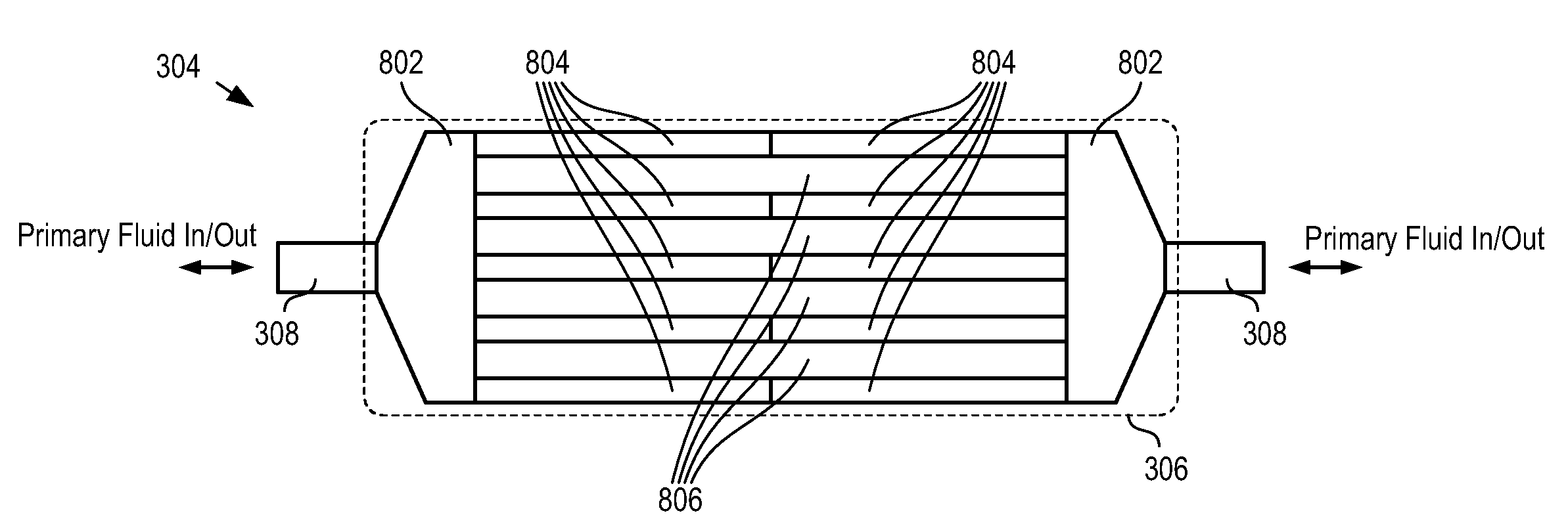
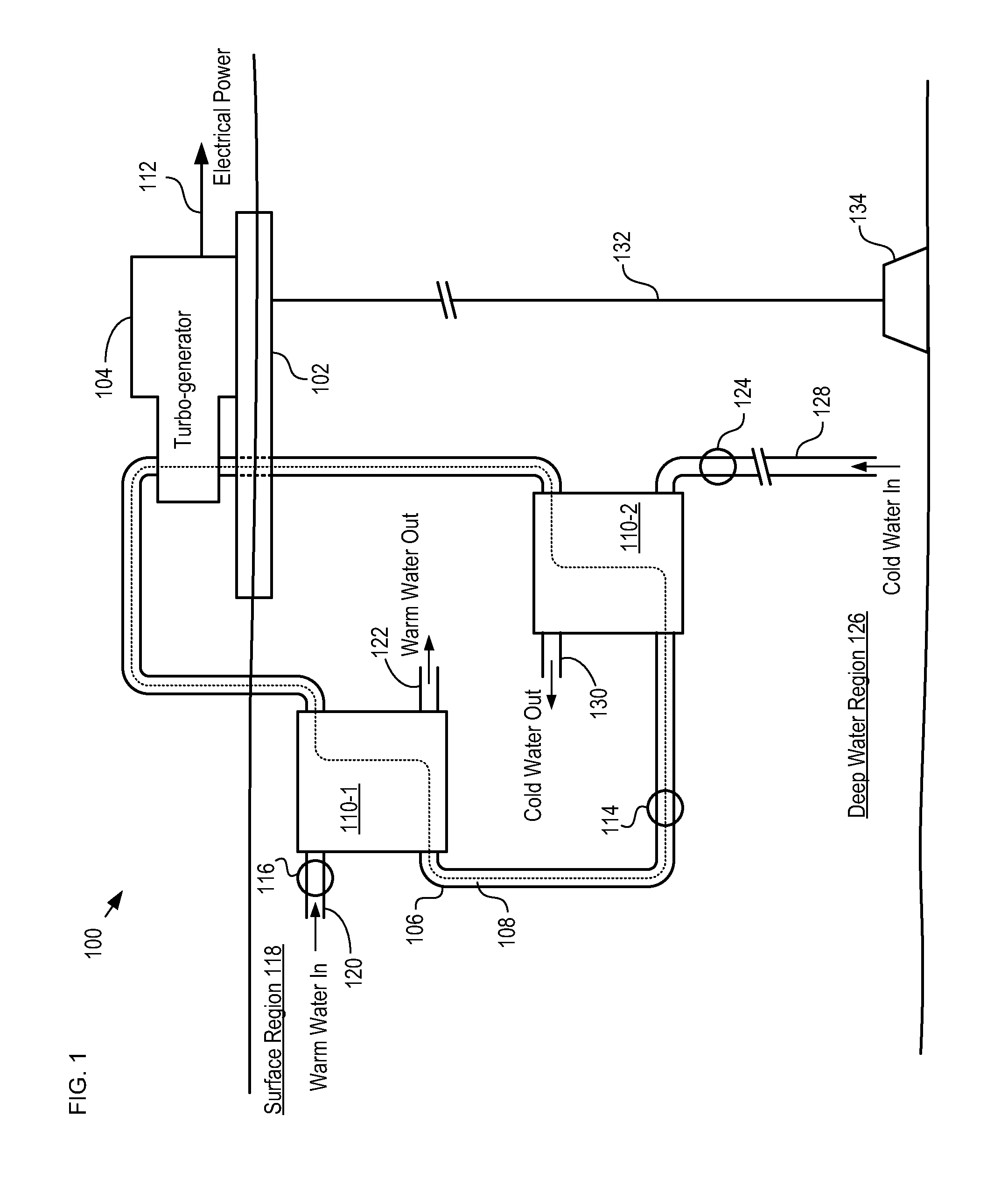
[0039]FIG. 1 depicts a schematic diagram of an OTEC power generation system in accordance with an illustrative embodiment of the present invention. OTEC system 100 comprises turbogenerator 104, closed-loop conduit 106, heat exchanger 110-1, heat exchanger 110-2, pumps 114, 116, and 124, and conduits 120, 122, 128, and 130.

[0040]Turbo-generator 104 is a conventional turbine-driven generator. Turbogenerator 104 is mounted on floating platform 102, which is a conventional floating energy-plant platform. Platform 102 is anchored to the ocean floor by mooring line 132 and anchor 134, which is embedded in the ocean floor. In some instances, platform 102 is not anchored to the ocean floor but is allowed to drift. Such a system is sometimes referred to as a “grazing plant.”

[0041]In typical operation, pump 114 pumps a primary fluid (i.e., working fluid 108), in liquid form, through closed-loop conduit 106 to heat exchanger 110-1. Ammonia is often used as working fluid 108 in OTEC systems; ho...


PUM

PropertyMeasurementUnit
Densityaaaaaaaaaa
Corrosion propertiesaaaaaaaaaa
Electrical conductoraaaaaaaaaa

Abstract

A heat exchanger for thermally coupling a first fluid and second fluid is disclosed. The heat exchanger comprises plates comprising cores of thermally conductive graphite foam. A plurality of conduits for conveying the first fluid is formed in each core. Each plate further comprises thermally conductive barriers that sandwich the core, wherein the barriers are substantially impervious to r the first fluid and second fluid. Plates are stacked in a frame such that the frame and plates collectively define a plurality of channels for conveying the second fluid. Heat is exchanged between the primary fluid and the secondary fluid through the graphite-foam cores and barriers.
Heat exchangers in accordance with the present invention can be lighter, have improved ratio of heat transfer surface density to heat exchanger volume, be lower cost, and/or be smaller for a given heat transfer capability than prior-art heat exchangers.

Description

CROSS REFERENCE TO RELATED APPLICATIONS[0001]This case claims priority of U.S. Provisional Patent Application U.S. 61 / 145,996, which was filed on Jan. 21, 2009 (Attorney Docket: 711-246US), and which is incorporated herein by reference.[0002]In addition, the underlying concepts, but not necessarily the language, of the following case is incorporated by reference:[0003]U.S. patent application Ser. No. 12 / 484,542, filed Jun. 5, 2009 (Attorney Docket: 711-231US).[0004]If there are any contradictions or inconsistencies in language between this application and one or more of the cases that have been incorporated by reference that might affect the interpretation of the claims in this case, the claims in this case should be interpreted to be consistent with the language in this case.FIELD OF THE INVENTION[0005]The present invention relates to energy conversion in general, and, more particularly, to heat exchangers.BACKGROUND OF THE INVENTION[0006]Patent application Ser. No. 12 / 484,542, fil...

Claims


Application Information

Patent Timeline
IPC IPC(8): F28F3/12B21D53/02
CPCF24J3/06Y10T29/49368F28D9/0081F28F13/003F28F13/08F28F21/02F28F21/067F28F21/084F28F2245/00F28F2275/025F28F2275/062Y02E10/34F28F2255/143Y10T29/4935F28D1/022F24V50/00Y02E10/30
Inventor NAGURNY, NICHOLAS J.QUARLES, KELVIN D.BAR-COHEN, AVRAM
Owner LOCKHEED MARTIN CORP
Why Eureka
Try Eureka