

Slave Cylinder for a Vibration-Damped Hydraulic Force Transmission System, Particularly a Hydraulic Clutch Actuating System for Motor Vehicles
- Summary
- Abstract
- Description
- Claims
- Application Information
AI Technical Summary
Benefits of technology
Problems solved by technology
Method used
Image

Examples
first embodiment
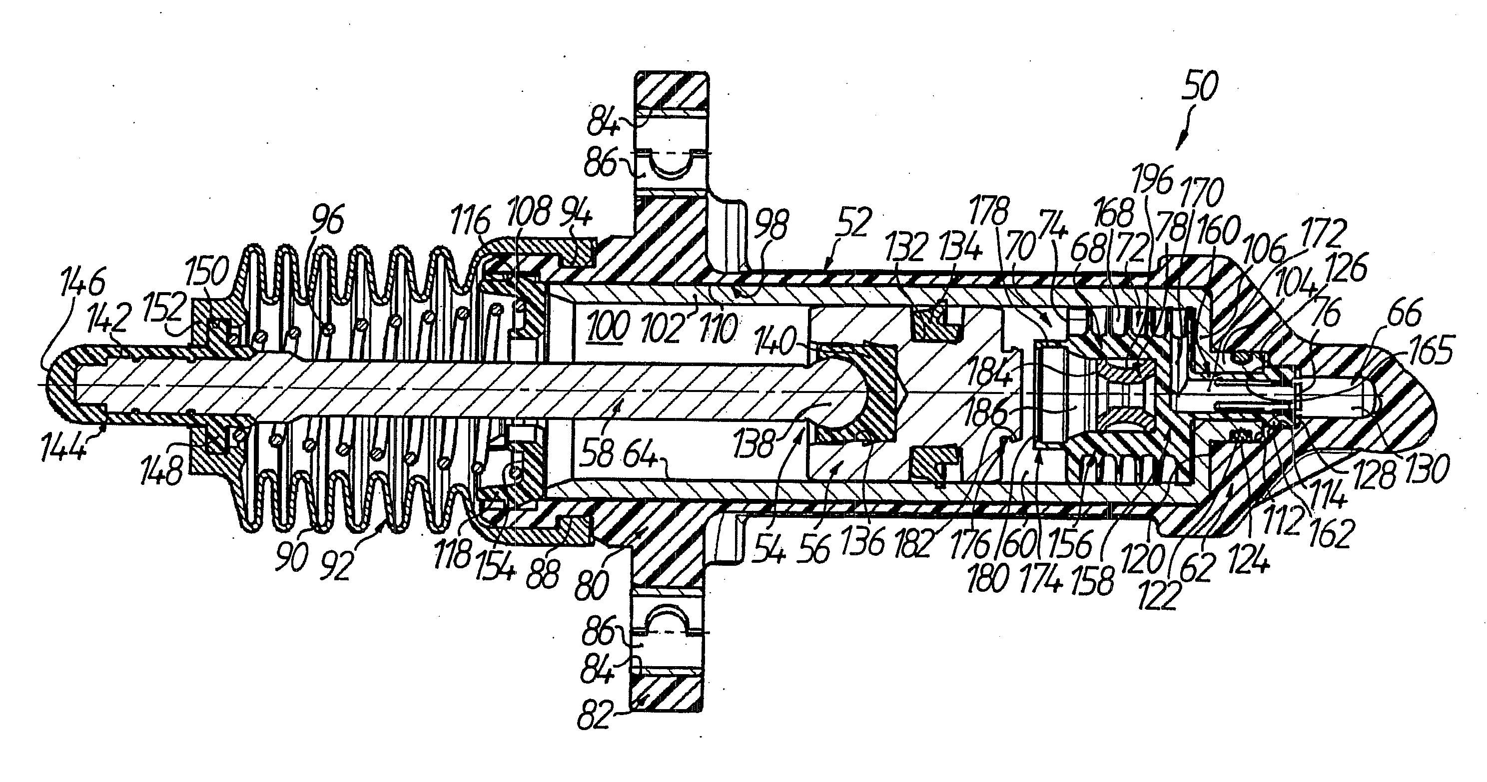
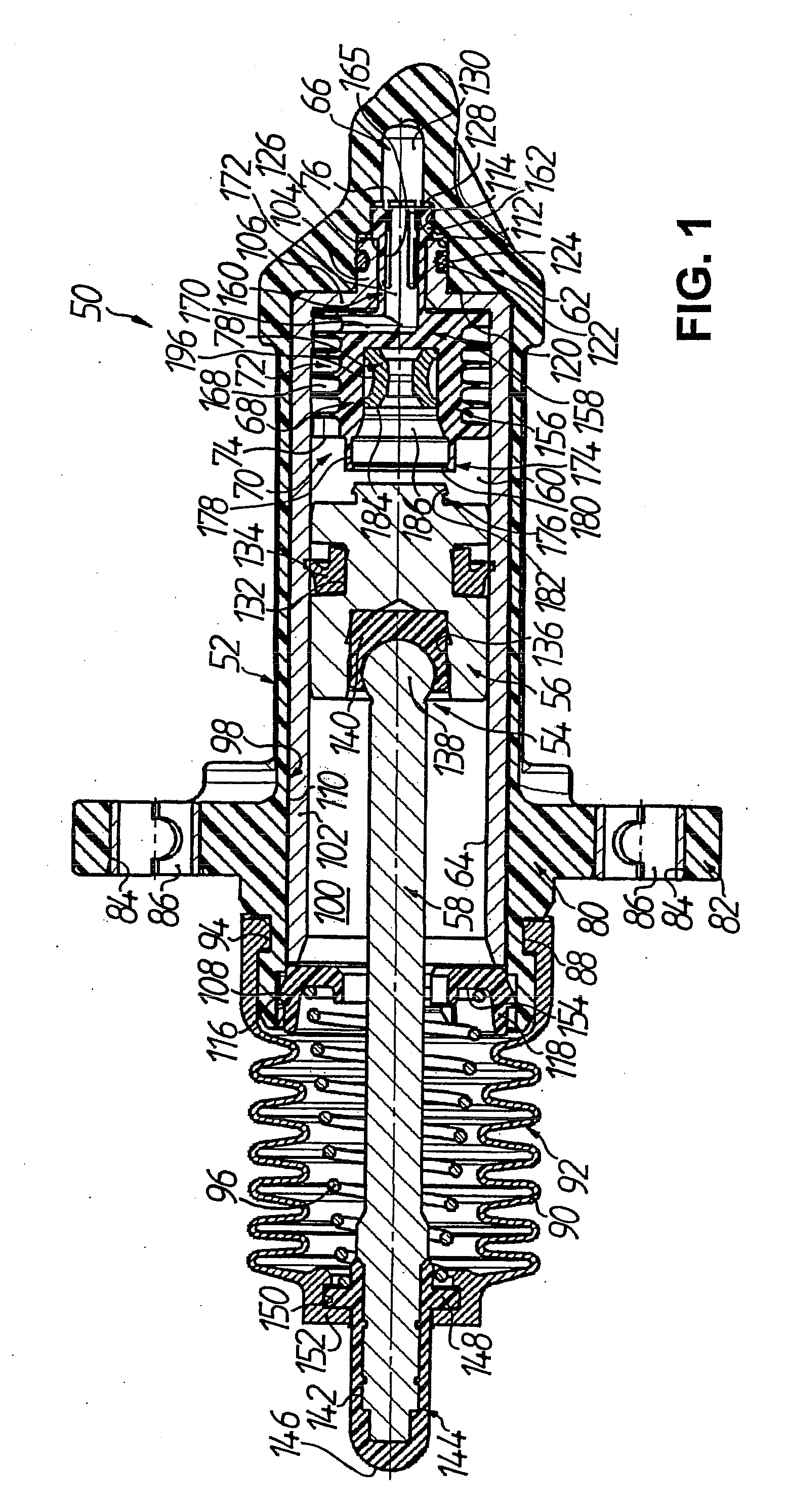
[0039]FIG. 1 shows a slave cylinder 50 for a vibration-damped hydraulic force transmission system, namely a vibration-damped clutch actuating system for motor vehicles. The slave cylinder 5 has a cylinder housing which is denoted generally by 52 and in which a piston subassembly54 is received to be longitudinally displaceable, the subassembly comprising a piston 56 and a piston rod 58 connected with the piston 56 at least rigidly in tension and compression, thus to be effective in terms of actuation. Disposed in the cylinder housing 52 is a pressure chamber 60 which is bounded on the lefthand side in FIG. 1 in variable manner by the piston 56, on the righthand side in FIG. 1 in fixed manner by a housing base 62 of the cylinder housing 52, and radially outwardly in fixed manner by a circumferential wall 64 of the cylinder housing 52. The pressure chamber 60 can be selectably acted on by a pressure medium, for example brake fluid, by way of a pressure connection 66, which is provided ...
third embodiment
[0063]By contrast, in the third embodiment illustrated in FIG. 11 a volume receiving means 78 according to FIGS. 8 and 9 is inserted in the blind bore 184 of the insert member 68. In exchange, the device 70 for reducing pressure pulses is here not provided with a channel forming an additional conduit path in the afore-described sense; there is quasi a direct, unprolonged connection between pressure chamber 60 and pressure connection 66 and, in particular, by way of a cross-sectionally large annular space 200, which is bounded at the inner circumference by the fastening section 174 and by the outer circumference—with the same outer diameter by comparison therewith—of the shroud section 156 of the insert member 68 and at the outer circumference by the circumferential wall 64 of the cylinder housing 52, as well as by way of the sections 170 and 172 in the base 158 or projection 160 of the insert member 68. In this regard the connecting section 170, in the installed position of the slav...
fourth embodiment
[0066]In the fourth embodiment illustrated in FIGS. 12 to 17 the insert member 68, which is again inserted in the pressure chamber 60 and secured in the pressure connection 66, comprises an inner insert 202 of substantially pot-shaped construction, with (see, in particular, FIGS. 13, 15 and 17) an inner insert shroud section 204 and an inner insert base 206. Formed between the shroud section 156 of the insert member 68 and the inner insert shroud section 204 is a helically extending helix section prolongation 208, one end of which is according to FIGS. 13 and 15 in fluid connection with the (outer) helix section 168 by way of the connecting section 170 and the other end of which is in fluid connection with an interior space 210 of the inner insert 202 by way of a passage 209, which interior space in turn communicates with the pressure connection 66 by way of the end section 172 in the extension 160. In that case the helix section prolongation 208 is again formed at the outer circumf...
PUM
 Abstract
Description
Claims
Application Information