Lubricating oil cooling device for traveling speed reduction gear

a technology of lubricating oil and cooling device, which is applied in the direction of analogue processes, machines/engines, instruments, etc., can solve the problems of affecting the efficiency of the oil cooler, requiring significant time and labor, and a long time-consuming and labor-intensive replacement process, so as to achieve optimal motor control, prevent damage to the oil cooler, and prevent damage effectively

Active Publication Date: 2010-07-29
NIHON KENKI CO LTD
View PDF5 Cites 30 Cited by
  • Summary
  • Abstract
  • Description
  • Claims
  • Application Information

AI Technical Summary

Benefits of technology

[0012]An object of the present invention, having been completed by addressing the issues discussed above, is to provide a traveling speed reduction gear lubricating oil cooling device that allows the lubricating oil temperature sensor to be installed outside the wheel mounting sleeve without inducing damage and the like to the oil cooler even when the work vehicle is engaged in operation in a cold work environment that allows the lubricating oil pump to be started up with a relatively small motor and enables desirable temperature control for the lubricating oil.
[0048]In addition, even if the output pressure at the lubricating oil pump rises to a level equal to or greater than the reference output pressure, the operation is allowed to continue in the decelerated state without stopping the lubricating oil pump, and as a result, the lubricating oil in the wheel mounting sleeve is continuously drawn out. In other words, by slowing the drive motor instead of stopping the lubricating oil pump, an undesirable decrease in the lubricating oil temperature can be prevented more effectively and thus, even better drive motor speed control is enabled.

Problems solved by technology

However, if the temperature sensor installed in the wheel mounting sleeve for direct lubricating oil temperature detection malfunctions, the temperature sensor will have to be removed by disengaging the wheels from the wheel mounting sleeve and also removing the traveling motor from the wheel mounting sleeve.
Since the wheels of the large work vehicle are heavy and large, measuring up to, for instance, 4 m in diameter, the replacement process is bound to be a costly process, requiring a significant length of time and significant labor.
In addition, since the work vehicle is idle while the temperature sensor is being replaced, the overall economic loss will be considerable.
For these reasons, it is not feasible to install the temperature sensor in the wheel mounting sleeve and, as an alternative, the temperature sensor may be installed in the lubricating oil circulation path outside the wheel mounting sleeve.
However, the following issues must be addressed when the work vehicle with the temperature sensor installed outside the wheel mounting sleeve is used in a low temperature environment, e.g., at high elevation locations with altitude of 4000 m or higher, in regions with cold climate, or during winter in regions with relatively high latitudes.
In other words, even as the lubricating oil inside the wheel mounting sleeve is heated to a level that requires cooling, the temperature detected by the temperature sensor installed outside the wheel mounting sleeve may not detect the temperature increase and, as a result, the heated lubricating oil may be allowed to overheat.
As the lubricating oil inside the wheel mounting sleeve remains overheated, the lowered viscosity will compromise its lubrication performance and the quality of the lubricating oil will be degraded.

Method used


Image

  • Lubricating oil cooling device for traveling speed reduction gear
  • Lubricating oil cooling device for traveling speed reduction gear
  • Lubricating oil cooling device for traveling speed reduction gear

Examples


Embodiment Construction

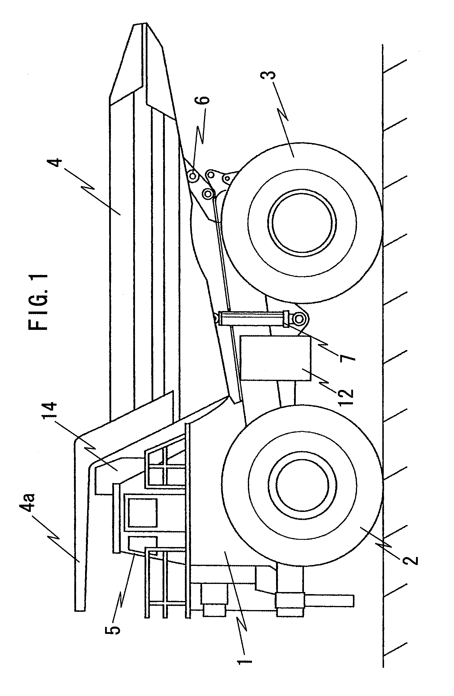
[0069]FIG. 1 is a side elevation of a large work vehicle that may adopt the present invention. The work vehicle in the example presented in the figure is a dump truck. The dump truck assuming a sturdy frame structure comprises a chassis 1 that includes front wheels 2 and rear wheels 3, a body 4 that functions as a load carrying platform and a cabin 5. The body 4 and the cabin 5 are disposed upon the chassis 1. The body 4 is a large container, the full length of which ranges 10˜13 m, used to carry heavy loads such as crushed rock or coal, in large volumes. The body 4 includes a hood 4a, formed as an integrated part thereof and located at the top thereof on the front side so as to cover the cabin 5 from above. The body 4 is tiltably mounted at the chassis 1 via a pin link unit 6 located on the rear side. Reference numeral 7 indicates a hoisting cylinder that hoists one end the body 4 up / down to tilt the body.

[0070]The front wheels 2 are steerable wheels via which the dump truck is ste...


PUM


Abstract

The present invention provides a traveling speed reduction gear lubricating oil cooling device that enables optimal temperature control for lubricating oil delivered via a lubricating oil pump that can be started up with a relatively small motor without running the risk of damage to an oil cooler in a cold work environment even when a temperature sensor that detects the temperature of the lubricating oil is installed outside a wheel mounting sleeve. During a startup operation, provided that the detected temperature at a traveling motor is higher than the reference temperature, the lubricating oil pump is driven at a speed in a lower speed range relative to the normal operation speed range. In addition, during the startup operation, the rotation speed of the drive motor for the lubricating oil pump is increased in correspondence to a rise in the temperature detected by a lubricating oil temperature detection sensor.

Description

TECHNICAL FIELD[0001]The present invention relates to a traveling speed reduction gear lubricating oil cooling device ideal for work vehicles such as large dump trucks used to carry, for instance, crushed rock excavated from mines or the like, and more specifically, it relates to a device that activates a lubricating oil cooling device at an initial startup.BACKGROUND ART[0002]A dump truck is a type of carrier vehicle that is normally equipped with a body disposed on the truck frame. The body, which can hold a heavy load, such as crushed rock, can be tilted in order to dump its contents. A traveling drive device that drives the drive wheels of the dump truck includes a tubular motor housing sleeve attached to the chassis and a drive motor such as an electric motor or a hydraulic motor that is disposed inside the motor housing sleeve and rotationally drives a rotating shaft. In addition, a tubular spindle is disposed toward the front end of the motor housing sleeve with a wheel mount...

Claims


Application Information

Patent Timeline
Patent Type & Authority Applications(United States)
IPC IPC(8): F01M5/00B60K17/04F16H57/02F16H57/04
CPCB60K17/046F16H57/0434
Inventor MURAHASHI, TAKAYOSHIMURAKAMI, OSAMUITOH, KENJI
Owner NIHON KENKI CO LTD
Why Eureka
Try Eureka